Isuzu Rodeo UE. Service manual — part 402

6E2–363
RODEO 6VD1 3.2L ENGINE DRIVEABILITY AND EMISSIONS
locks, improperly formed or damaged terminals, and
poor terminal-to-wire connection.
f
The TP Sensor shares a 5 Volt reference with the EGR
Valve.
If these codes are also set, it could indicate a
problem with the 5 Volt reference circuit or
components itself.
f
The TP Sensor share a ground with the EGR Valve and
the IAT Sensor.
f
Damaged harness – Inspect the wiring harness for
damage. If the harness appears to be OK, observe the
MAP display on the Tech 2 while moving connectors
and wiring harnesses related to the sensor. A change
in the display will indicate the location of the fault.
Reviewing the Failure Records vehicle mileage since the
diagnostic test last failed may help determine how often
the condition that caused the DTC to be set occurs. This
may assist in diagnosing the condition.
DTC P1107 –MAP Sensor Circuit Intermittent Low Voltage
Step
Action
Value(s)
Yes
No
1
Was the “On-Board Diagnostic (OBD) System Check”
performed?
—
Go to
Step 2
Go to
OBD
System
Check
2
Is DTC P0107 also set?
—
Go to
DTC
P0107 chart
first
Go to
Step 3
3
Is DTC P1122 also set?
—
Go to
Step 6
Go to
Step 4
4
Check for a poor 5 volt reference “A” circuit or MAP
signal circuit terminal connection at the MAP sensor.
Was a problem found?
—
Go to
Step 9
Go to
Step 5
5
Check the MAP signal circuit between the MAP sensor
connector and the PCM for an intermittent open or
short to ground.
Was a problem found?
—
Go to
Step 10
Go to
Step 8
6
Check for an intermittent short to ground on the 5 volt
reference “A” circuit between the PCM and the
following components:
f
MAP sensor
f
EGR valve
f
TP sensor
Was a problem found?
—
Go to
Step 10
Go to
Step 7
7
Check for a poor 5 volt reference “A” terminal
connection at the PCM.
Was a problem found?
—
Go to
Step 9
Go to
Step 8
8
Check for an intermittent open or a faulty splice in the 5
volt reference “A” circuit.
Was a problem found? (If no, start with the diagnosis
chart for other sensors in the circuit and see if 5V
returns.)
—
Go to
Step 10
Refer to
Diagnostic
Aids
9
Replace the faulty harness connector terminal(s) for
the 5 volt reference “A” circuit and/or the MAP signal
circuit as necessary.
Is the action complete?
—
Verify repair
—
10
Repair intermittent open/short circuit in the wiring
harness as necessary.
Is the action complete?
—
Verify repair
—
6E2–364
RODEO 6VD1 3.2L ENGINE DRIVEABILITY AND EMISSIONS
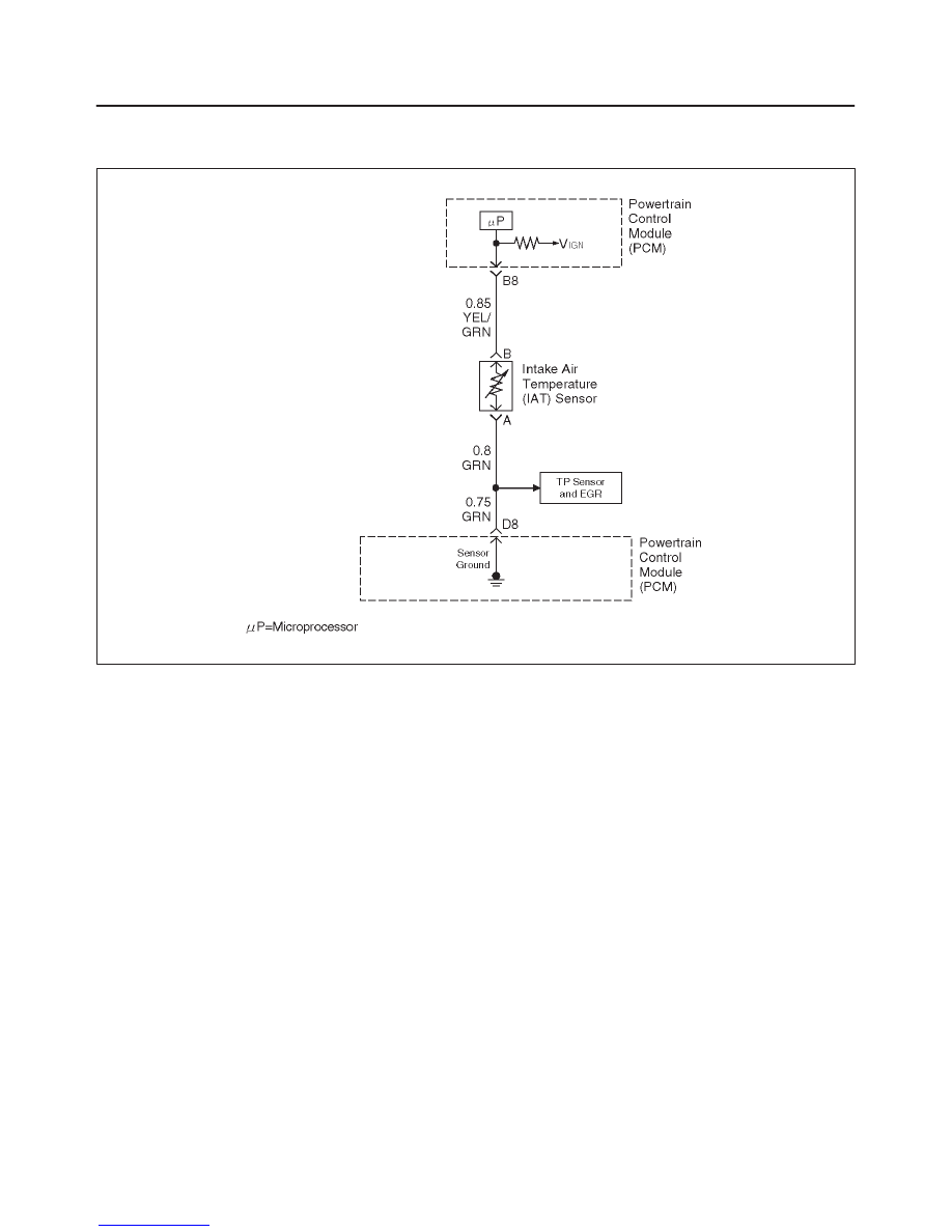
Diagnostic Trouble Code (DTC) P1111 IAT Sensor Circuit Intermittent High
Voltage
D06RW078
Circuit Description
The intake air temperature (IAT) sensor is a thermistor
which measures the temperature of the air entering the
engine. The powertrain control module (PCM) applies 5
volts through a pull-up resistor to the IAT sensor. When
the intake air is cold, the sensor resistance is high and the
PCM will monitor a high signal voltage on the IAT signal
circuit. If the intake air is warm, the sensor resistance is
lower causing the PCM to monitor a lower voltage. DTC
P1111 will set when the PCM intermittently detects an
excessively high signal voltage on the intake air
temperature sensor signal circuit.
Conditions for Setting the DTC
f
The engine has been running for over 4 minutes.
f
Vehicle speed is less than 20 mph (32 km/h).
f
Engine coolant temperature is above 60
°
C (140
°
F).
f
Mass air flow is less than 20g/second.
f
IAT signal voltage indicates and intake air temperature
intermittently less than –39
°
C (–38
°
F) (about 5 volts)
for approximately 2.5 seconds over a 25-second
period of time.
Action Taken When the DTC Sets
f
The PCM will substitute a default value for intake air
temperature.
f
The PCM will store conditions which were present
when the DTC set as Failure Records data only. This
information will not be stored as Freeze Frame data.
f
DTC P1111 does not illuminate the MIL.
Conditions for Clearing the MIL/DTC
f
A history DTC P1111 will clear after 40 consecutive
warm–up cycles have occurred without a fault.
f
DTC P1111 can be cleared by using the Tech 2 “Clear
Info” function or by disconnecting the PCM battery
feed.
Diagnostic Aids
Check for the following conditions:
f
Poor connection at PCM – Inspect harness connectors
for backed-out terminals, improper mating, broken
locks, improperly formed or damaged terminals, and
poor terminal-to-wire connection.
f
Damaged harness – Inspect the wiring harness for
damage. If the harness appears to be OK, observe the
IAT display on the Tech 2 while moving connectors and
wiring harnesses related to the IAT sensor. A change
in the IAT display will indicate the location of the fault.
Reviewing the Failure Records vehicle mileage since the
diagnostic test last failed may help determine how often
the condition that caused the DTC to be set occurs. This
may assist in diagnosing the condition.

6E2–365
RODEO 6VD1 3.2L ENGINE DRIVEABILITY AND EMISSIONS
Intake Air Temperature Sensor
°
C
°
F
OHMS
Temperature vs. Resistance Values (approximate)
100
212
177
80
176
332
60
140
667
45
113
1188
35
95
1802
25
77
2796
15
59
4450
5
41
7280
–5
23
12300
–15
5
21450
–30
–22
52700
–40
–40
100700

6E2–366
RODEO 6VD1 3.2L ENGINE DRIVEABILITY AND EMISSIONS
DTC P1111 –IAT Sensor Circuit Intermittent High Voltage
Step
Action
Value(s)
Yes
No
1
Was the “On-Board Diagnostic (OBD) System Check”
performed?
—
Go to
Step 2
Go to
OBD
System
Check
2
Is DTC P0113 also set?
—
Go to
DTC
P0113 chart
first
Go to
Step 3
3
Is DTC P1106, P1115, and/or P1121 also set?
—
Go to
Step 6
Go to
Step 4
4
1. Check for a poor sensor ground circuit terminal
connection at the IAT sensor.
2. If a problem is found, repair as necessary.
Was a problem found?
—
Verify repair
Go to
Step 5
5
1. Check for a poor IAT signal circuit terminal
connection at the IAT sensor.
2. If a problem is found, repair as necessary.
Was a problem found?
—
Verify repair
Go to
Step 6
6
1. Check the IAT signal circuit between the IAT sensor
connector and the PCM for an intermittent open.
2. If a problem is found, repair as necessary.
Was a problem found?
—
Verify repair
Go to
Step 7
7
1. Check the IAT signal circuit between the IAT sensor
connector and the PCM for an intermittent short to
voltage.
2. If a problem is found, repair as necessary.
Was a problem found?
—
Verify repair
Go to
Step 8
8
1. Check for a poor sensor ground circuit terminal
connection at the PCM.
2. If a problem is found, repair as necessary.
Was a problem found?
—
Verify repair
Go to
Step 9
9
1. Check for an intermittent open or a faulty splice in
the sensor ground circuit.
2. If a problem is found, repair as necessary.
Was a problem found?
—
Verify repair
Refer to
Diagnostic
Aids
Нет комментариевНе стесняйтесь поделиться с нами вашим ценным мнением.
Текст