Isuzu Rodeo UE. Service manual — part 22
1A–58 HEATING, VENTILATION AND AIR CONDITIONING (HVAC)
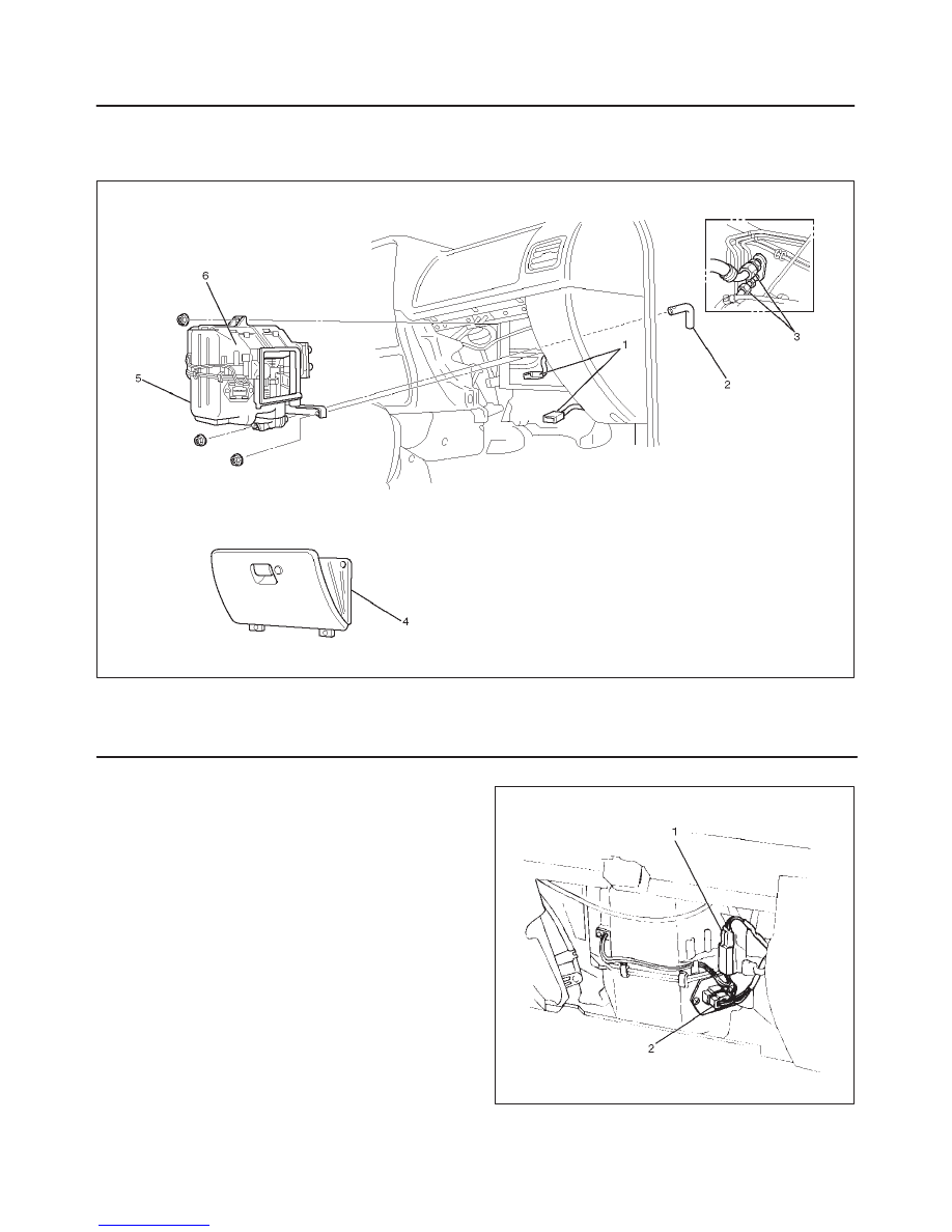
Evaporator Assembly
Evaporator Assembly and Associated Parts
874RW007
Legend
(1) Resistor and Electronic Thermostat Connector
(2) Drain Hose
(3) Refrigerant Line
(4) Glove Box
(5) Evaporator Assembly
Removal
1. Disconnect the battery ground cable.
2. Discharge and recover refrigerant.
f
Refer to Refrigerant Recovery in this section.
3. Remove glove box.
4. Disconnect resistor (2) and electronic thermostat
connector (1).
840RS005
5. Disconnect drain hose.
HEATING, VENTILATION AND AIR CONDITIONING (HVAC) 1A–59
6. Disconnect refrigerant line.
f
Use a back-up wrench when disconnecting and
reconnecting the refrigerant lines.
f
When removing the refrigerant line connected part,
the connecting part should immediately be plugged
or capped to prevent foreign matter from being
mixed into the line.
7. Remove evaporator assembly.
Installation
To install, follow the removal steps in the reverse order,
noting the following points:
1. To install a new evaporator assembly, add 50cc
(1.7 fl. oz.) of new compressor oil to the new core.
2. Tighten the refrigerant outlet line to the specified
torque.
Torque: 25 N
•
m (18 lb ft)
3. Tighten the refrigerant inlet line to the specified
torque.
Torque: 15 N
•
m (11 lb ft)
4. O-rings cannot be reused. Always replace with new
ones.
5. Be sure to apply new compressor oil to the O-rings
when connecting lines.
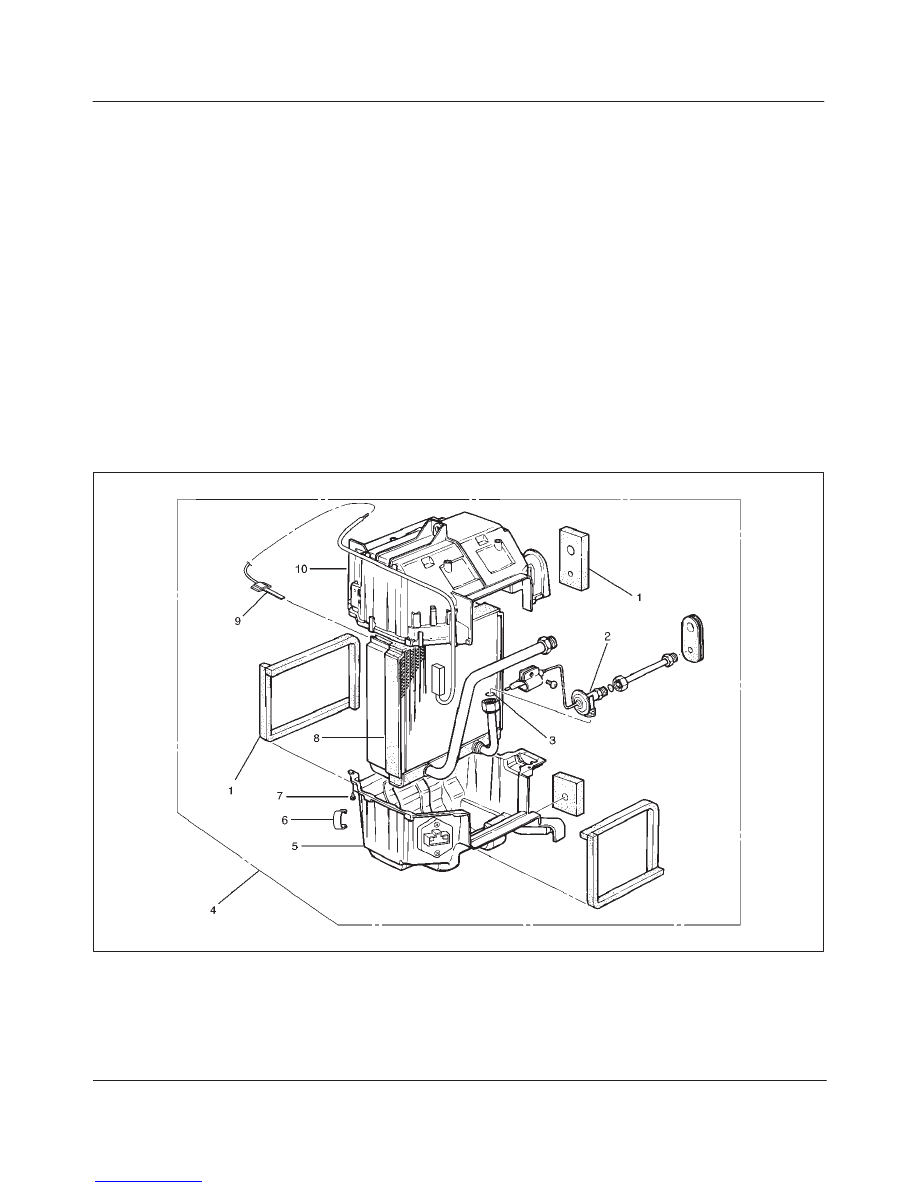
Electronic Thermostat, Evaporator Core and/or Expansion Valve
Disassembled View
874RX001
Legend
(1) Lining
(2) Expansion Valve
(3) O-ring
(4) Evaporator Assembly
(5) Lower Case
(6) Clip
(7) Attaching Screw
(8) Evaporator Core
(9) Electronic Thermostat
(10) Upper Case
1A–60 HEATING, VENTILATION AND AIR CONDITIONING (HVAC)
Removal
1. Disconnect the battery ground cable.
2. Discharge and recover refrigerant.
f
Refer to Refrigerant Recovery in this section.
3. Remove evaporator assembly.
f
Refer to Evaporator Assembly in this section.
4. Remove the electronic thermostat sensor fixing clip.
Pull the sensor from the evaporator assembly.
5. Remove clip.
6. Remove attaching screw.
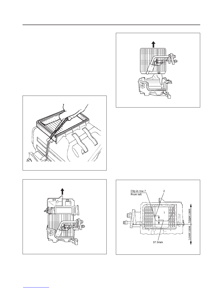
7. Remove upper case.
8. Remove lower case.
f
Slit the case parting face with a knife since the lining
is separated when removing the evaporator.
874RS006
f
Lift to remove the upper case.
874RW001–1
9. Remove evaporator core.
874RW002–1
10. Remove expansion valve.
f
Tear off the insulator carefully.
f
Remove the sensor fixing clip.
f
Use a back-up wrench when disconnecting all
refrigerant pipes.
Installation
To install, follow the removal steps in the reverse order,
noting the following points:
1. The sensor is installed on the core with the clip.
2. The sensor must not interfere with the evaporator
core.
3. When installing the new evaporator core, install the
thermo sensor (2) to the evaporator core (1) specified
position with the clip in the illustration.
874RX004
HEATING, VENTILATION AND AIR CONDITIONING (HVAC) 1A–61
4. O-rings cannot be reused. Always replace with new
ones.
5. Be sure to apply new compressor oil to the O-rings
when connecting lines.
6. Be sure to install the sensor and the insulator on the
place where they were before.
7. To install a new evaporator core, add 50cc (1.7 fl. oz.)
of new compressor oil to the new core.
8. Tighten the refrigerant lines to the specified torque.
Refer to Main Data and Specifications for Torque
Specifications in this section.
9. Apply an adhesive to the parting face of the lining
when assembling the evaporator assembly.
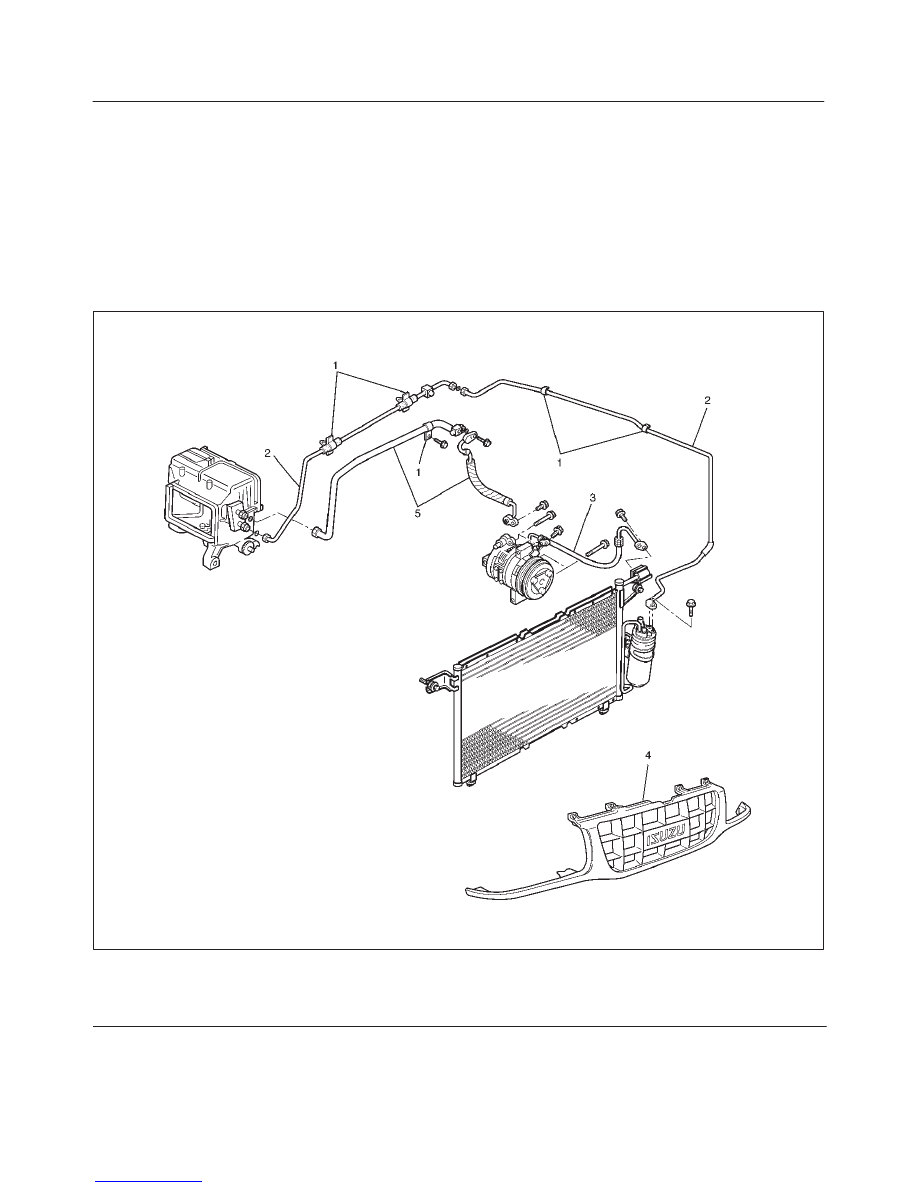
Refrigerant Line
Refrigerant Line and Associated Parts
852RX001
Legend
(1) Clip and Clamp
(2) Liquid Line (High-Pressure Pipe)
(3) Discharge Line (High-Pressure Hose)
(4) Radiator Grille
(5) Suction Line (Low-Pressure Pipe)
Нет комментариевНе стесняйтесь поделиться с нами вашим ценным мнением.
Текст