Isuzu Rodeo UE. Service manual — part 21
1A–54 HEATING, VENTILATION AND AIR CONDITIONING (HVAC)
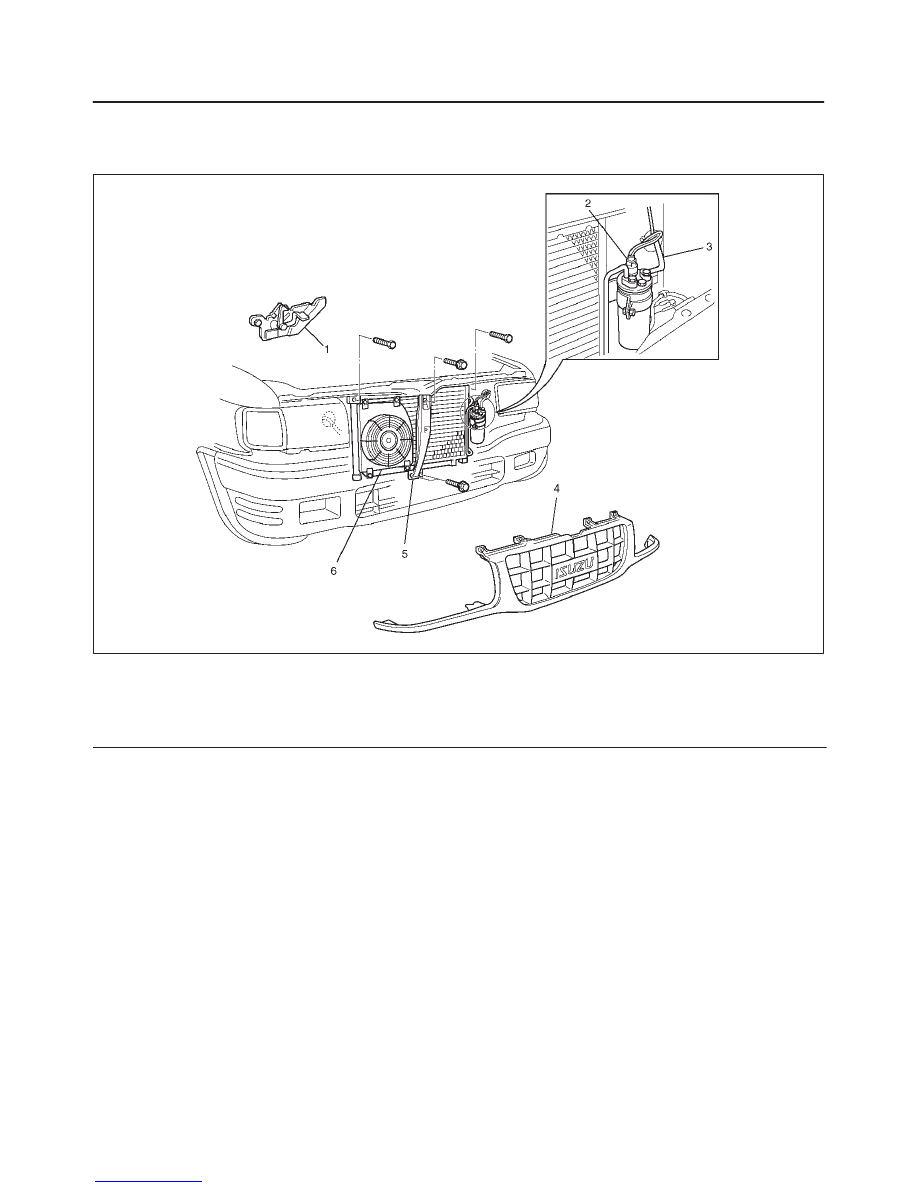
Condenser Assembly
Condenser Assembly and Associated Parts
875RW008
Legend
(1) Engine Hood Lock
(2) Pressure Switch Connector
(3) Refrigerant Line
(4) Radiator Grille
(5) Engine Hood Front End Stay
(6) Condenser Assembly
Removal
1. Disconnect the battery ground cable.
2. Discharge and recover refrigerant.
f
Refer to Refrigerant Recovery in this section.
3. Remove radiator grille.
4. Remove engine hood front end stay.
5. Remove engine hood lock.
f
Apply setting mark to the engine hood lock fixing
position before removing it.
6. Disconnect pressure switch connector.
7. Disconnect refrigerant line.
f
When removing the line connector, the connecting
part should immediately be plugged or capped to
prevent foreign matter from being mixed into the
line.
8. Remove condenser assembly.
f
Handle with care to prevent damaging the
condenser or radiator fin.
Installation
1. Install condenser assembly.
f
If installing a new condenser, be sure to add 30cc
(1.0 fl. oz.) of new compressor oil to a new one.
f
Tighten the condenser fixing bolts to the specified
torque.
Torque: 6 N
•
m (52 lb in)
2. Connect refrigerant line.
f
Tighten the inlet line connector fixing bolt to the
specified torque.
Torque: 15 N
•
m (11 lb ft)
f
Tighten the outlet line connector fixing bolt to the
specified torque.
Torque: 6 N
•
m (52 lb in)
f
O-rings cannot be reused. Always replace with new
ones.
HEATING, VENTILATION AND AIR CONDITIONING (HVAC) 1A–55
f
Be sure to apply new compressor oil to the O-rings
when connecting the refrigerant line.
3. Connect pressure switch connector.
4. Install engine hood lock.
5. Install engine hood front end stay.
6. Install radiator grille.
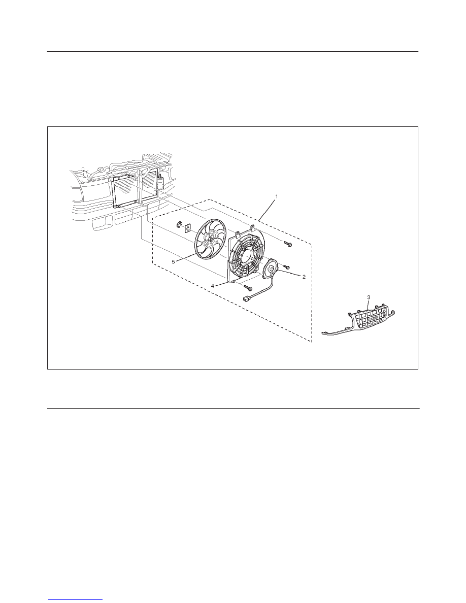
Condenser Fan Motor
Condenser Fan Motor and Associated Parts
875RW009
Legend
(1) Condenser Fan Assembly
(2) Condenser Fan Motor
(3) Radiator Grille
(4) Shroud
(5) Fan
Removal
1. Disconnect the battery ground cable.
2. Discharge and recover refrigerant.
f
Refer to Refrigerant Recovery in this section.
3. Remove radiator grille.
4. Remove condenser fan assembly.
f
Disconnect the fan motor connector and remove
the 4 fixing bolts.
5. Remove shroud.
f
Remove the 3 fixing nuts.
f
Loosen the condenser fixing nut and disconnect the
fan motor connector from bracket.
6. Remove fan.
f
Remove the fan fixing C-ring and plate.
7. Remove condenser fan motor.
Installation
To install, follow the removal steps in the reverse order,
noting the following point.
1. Route the fan motor harness in its previous position,
and fix it securely with clip and bracket.

1A–56 HEATING, VENTILATION AND AIR CONDITIONING (HVAC)
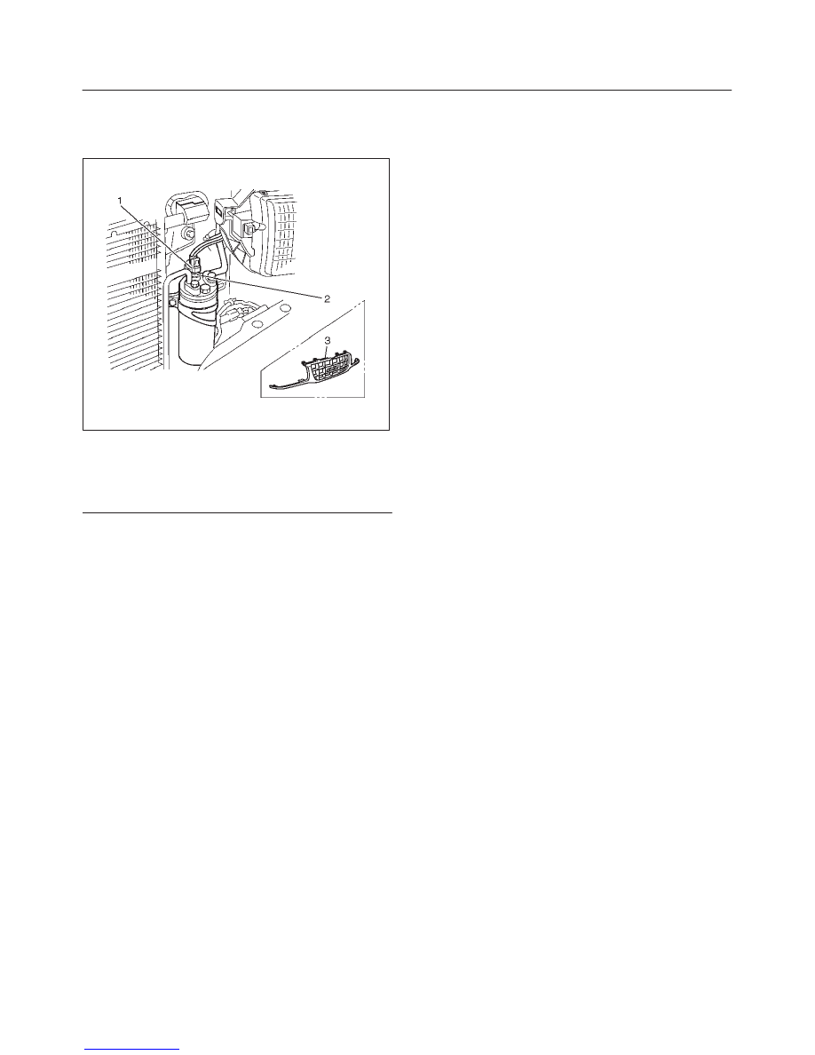
Receiver / Drier
Receiver / Drier and Associated Parts
875RW011
Legend
(1) Pressure Switch Connector
(2) Refrigerant Line
(3) Radiator Grille
(4) Receiver / Drier
(5) Bracket Bolt
Removal
1. Disconnect the battery ground cable.
2. Discharge and recover refrigerant.
f
Refer to Refrigerant Recovery in this section.
3. Remove radiator grille.
4. Disconnect pressure switch connector.
5. Disconnect refrigerant line.
f
When removing the line connected part, the
connecting part should immediately be plugged or
capped to prevent foreign matter from being mixed
into the line.
6. Remove bracket bolt.
7. Remove receiver/drier.
f
Loosen the bolt, then, using care not to touch or
bend the refrigerant line, carefully pull out the
receiver/drier.
Installation
To install, follow the removal steps in the reverse order,
noting the following points:
1. If installing a new receiver/drier, be sure to add 30cc
(1.0 fl. oz.) of new compressor oil to a new one.
2. Put the receiver/drier in the bracket and connect with
the refrigerant line. Check that no excessive force is
imposed on the line. Fasten the bracket bolt to the
receiver/drier.
3. Tighten the refrigerant line to the specified torque.
Torque: 6 N
•
m (52 lb in)
4. O-rings cannot be reused. Always replace with new
ones.
5. Be sure to apply new compressor oil to the O-rings
when connecting the refrigerant line.
HEATING, VENTILATION AND AIR CONDITIONING (HVAC) 1A–57
Pressure Switch
Pressure Switch and Associated Parts
875RW012
Legend
(1) Pressure Switch Connector
(2) Pressure Switch
(3) Radiator Grille
Removal
1. Disconnect the battery ground cable.
2. Discharge and recover refrigerant.
f
Refer to “Refrigerant Recovery in this section.
3. Remove radiator grille.
4. Disconnect pressure switch connector.
5. Disconnect pressure switch.
f
When removing the switch connected part, the
connecting part should immediately be plugged or
capped to prevent foreign matter from being mixed
into the line.
Installation
To install, follow the removal steps in the reverse order,
noting the following point:
1. O-ring cannot be reused. Always replace with a new
one.
2. Be sure to apply new compressor oil to the O-ring
when connecting pressure switch.
3. Tighten the pressure switch to the specified torque.
Torque: 13 N
•
m (113 lb in)
Нет комментариевНе стесняйтесь поделиться с нами вашим ценным мнением.
Текст