Isuzu Rodeo UE. Service manual — part 276
6A–17
ENGINE MECHANICAL (6VD1 3.2L)
Fuel Consumption Excessive
Condition
Possible cause
Correction
Trouble in fuel system
Mixture too rich or too lean due to
trouble in fuel injection system
Refer to “Abnormal Combustion”
Fuel cut function does not work
Refer to “Abnormal Combustion”
Trouble in ignition system
Misfiring or abnormal combustion
due to trouble in ignition system
Refer to “Hard Start” or “Abnormal
Combustion”
Others
Engine idle speed too high
Reset Idle Air Control Valve
Returning of accelerator control
sluggish
Correct
Fuel system leakage
Correct or replace
Clutch slipping
Correct
Brake drag
Correct
Selection of transmission gear
incorrect
Caution operator of incorrect gear
selection
Excessive Exhaust Gas
Recirculation flow due to trouble in
Exhaust Gas Recirculation system
Refer to “Abnormal Combustion”
Lubrication Problems
Condition
Possible cause
Correction
Oil pressure too low
Wrong oil in use
Replace with correct engine oil
Relief valve sticking
Replace
Oil pump not operating properly
Correct or replace
Oil pump strainer clogged
Clean or replace strainer
Oil pump worn
Replace
Oil pressure gauge defective
Correct or replace
Crankshaft bearing or connecting
rod bearing worn
Replace
Oil contamination
Wrong oil in use
Replace with correct engine oil
Oil filter clogged
Replace oil filter
Cylinder head gasket damage
Replace gasket
Burned gases leaking
Replace piston and piston rings or
cylinder body assembly
Oil not reaching valve system
Oil passage in cylinder head or
cylinder body clogged
Clean or correct
Engine Oil Pressure Check
1. Check for dirt, gasoline or water in the engine oil.
a. Check the viscosity of the oil.
b. Check the viscosity of the oil.
c. Change the oil if the viscosity is outside the
specified standard.
d. Refer to the “Maintenance and Lubrication” section
of this manual.
2. Check the engine oil level.
The level should fall somewhere between the “ADD”
and the “FULL” marks on the oil level dipstick.
If the oil level does not reach the “ADD” mark on the
oil level dipstick, engine oil must be added.
3. Remove the oil pressure unit.
4. Install an oil pressure gauge.
5. Start the engine and allow the engine to reach normal
operating temperature (About 80
°
C).
6. Measure the oil pressure.
Oil pressure should be:
392–550 kPa (56.9–80.4 psi) at 3000 rpm.
7. Stop the engine.
8. Remove the oil pressure gauge.
9. Install the oil pressure unit.
10. Start the engine and check for leaks.
6A–18
ENGINE MECHANICAL (6VD1 3.2L)
Malfunction Indicator Lamp
The instrument panel “CHECK ENGINE” Malfunction In-
dicator Lamp (MIL) illuminates by self diagnostic system
when the system checks the starting of engine, or senses
malfunctions.
Condition
Possible cause
Correction
“CHECK ENGINE” MIL does not
illuminate at the starting of engine
Bulb defective
Replace
illuminate at the starting of engine
MIL circuit open
Correct or replace
Command signal circuit to operate
self diagnostic system shorted
Correct or replace
Powertrain Control Module (PCM)
cable loosely connected,
disconnected or defective
Correct or replace
PCM defective
Replace
“CHECK ENGINE” MIL illuminates,
and stays on
Deterioration of heated oxygen
sensor internal element
Replace
Heated oxygen sensor connector
terminal improper contact
Reconnect properly
Heated oxygen sensor lead wire
shorted
Correct
Heated oxygen sensor circuit open
Correct or replace
Deterioration of engine coolant
temperature sensor internal element
Replace
Engine coolant temperature sensor
connector terminal improper contact
Reconnect properly
Engine coolant temperature sensor
lead wire shorted
Correct
Engine coolant temperature sensor
circuit open
Correct or replace
Throttle position sensor open or
shorted circuits
Correct or replace
Deterioration of crankshaft position
sensor
Replace
Crankshaft position sensor circuit
open or shorted
Correct or replace
Vehicle speed sensor circuit open
Correct or replace
Manifold absolute pressure sensor
circuit open or shorted
Correct or replace
Intake air temperature sensor circuit
open or shorted
Correct or replace
Fuel injector circuit open or shorted
Correct or replace
PCM driver transistor defective
Replace PCM
Malfunctioning of PCM RAM
(Random Access Memory) or ROM
(Read Only Memory)
Replace PCM
6A–19
ENGINE MECHANICAL (6VD1 3.2L)
Cylinder Head Cover LH
Removal
1. Disconnect battery ground cable.
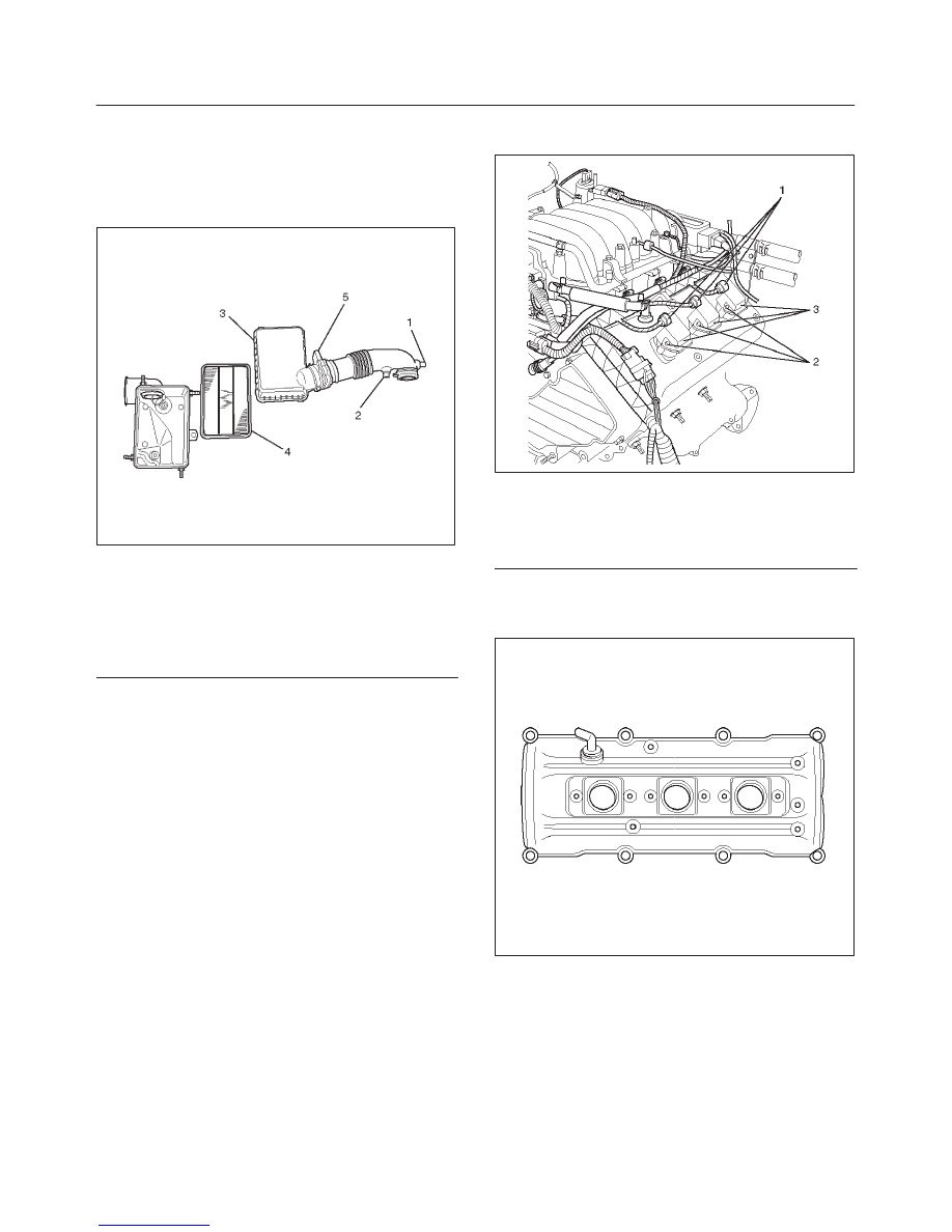
2. Remove air cleaner duct assembly.
130RW001
Legend
(1) Positive Crankcase Ventilation Hose Connector
(2) Intake Air Temperature Sensor
(3) Air Cleaner Duct Assembly
(4) Air Cleaner Element
(5) Mass Air Flow Sensor
3. Disconnect positive crankcase ventilation hose.
4. Remove camshaft angle sensor connector.
5. Remove ground cable fixing bolt on cylinder head
cover.
6. Ignition coil connector and ignition coil.
f
Disconnect the three connectors from the ignition
coils.
f
Remove harness bracket bolt on cylinder head
cover.
f
Remove fixing bolts on ignition coils.
060RW018
Legend
(1) Ignition Coil Connector
(2) Bolt
(3) Ignition Coil Assemblies
7. Remove fixing bolt for fuel injector harness bracket.
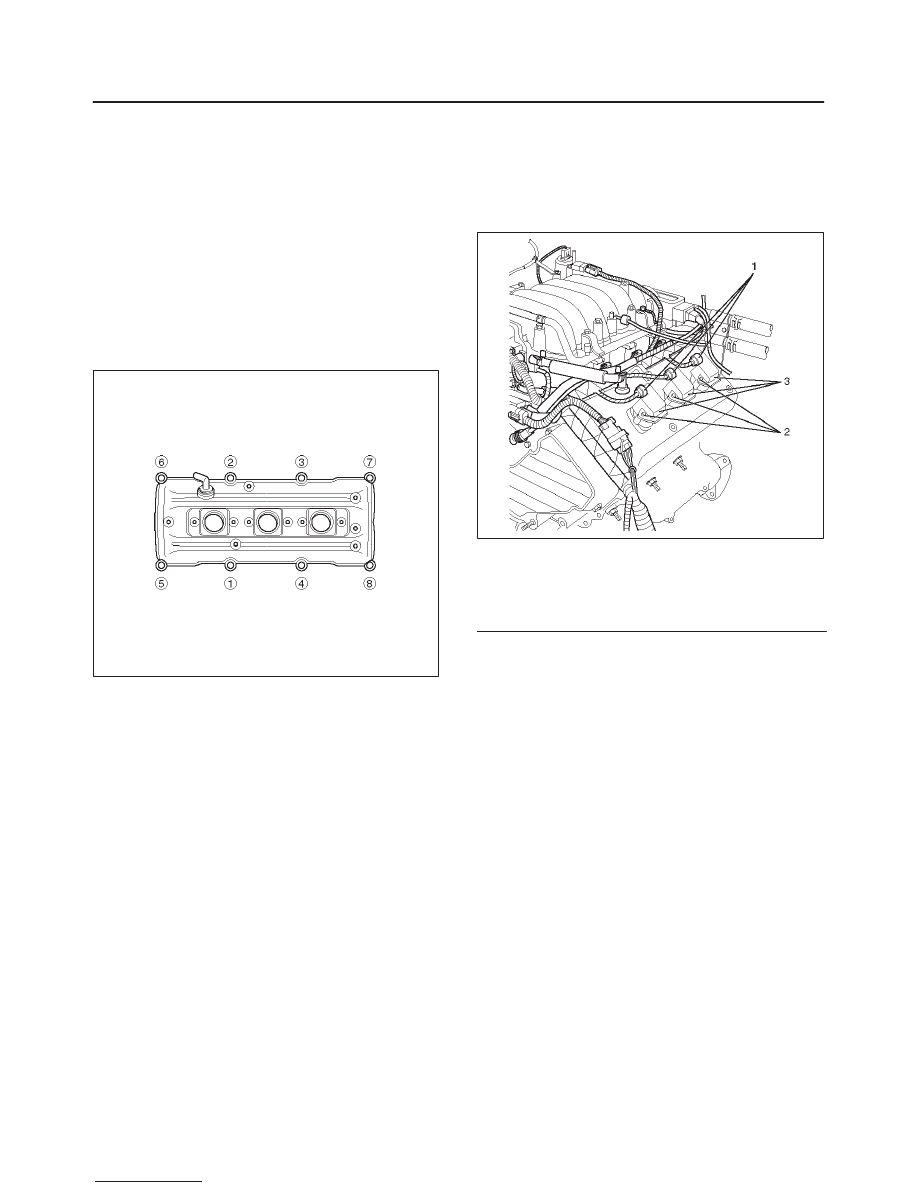
8. Remove eight fixing bolts, then the cylinder head
cover.
010RW001
6A–20
ENGINE MECHANICAL (6VD1 3.2L)
Installation
1. Install cylinder head cover.
f
Clean the sealing surface of cylinder head and
cylinder head cover to remove oil and sealing
materials completely.
f
Apply sealant (TB-1207B or equivalent) of bead
diameter 2-3 mm at eight place of arched area of
camshaft bracket on front and rear sides.
f
The cylinder head cover must be installed with in 5
minutes after sealant application to prevent
hardning of sealant.
f
Tighten bolts to the specified torque.
Torque : 9 N·m (80 lb in)
010RW006
2. Install fuel injection harness bracket and tighten bolt
to the specified torque.
Torque : 9 N·m (80 lb in)
3. Connect ignition coil connector and ignition coil, then
tighten bolt to the specified torque.
Torque : 4 N·m (35 lb in)
060RW018
Legend
(1) Ignition Coil Connector
(2) Bolt
(3) Ignition Coil Assembly
4. Connect ground cable and tighten bolts to the
specified torque.
Torque : 9 N·m (80 lb in)
5. Connect camshaft angle sensor connector.
6. Install positive crankcase ventilation hose.
7. Install air cleaner duct assembly.
Нет комментариевНе стесняйтесь поделиться с нами вашим ценным мнением.
Текст