Isuzu Rodeo UE. Service manual — part 277
6A–21
ENGINE MECHANICAL (6VD1 3.2L)
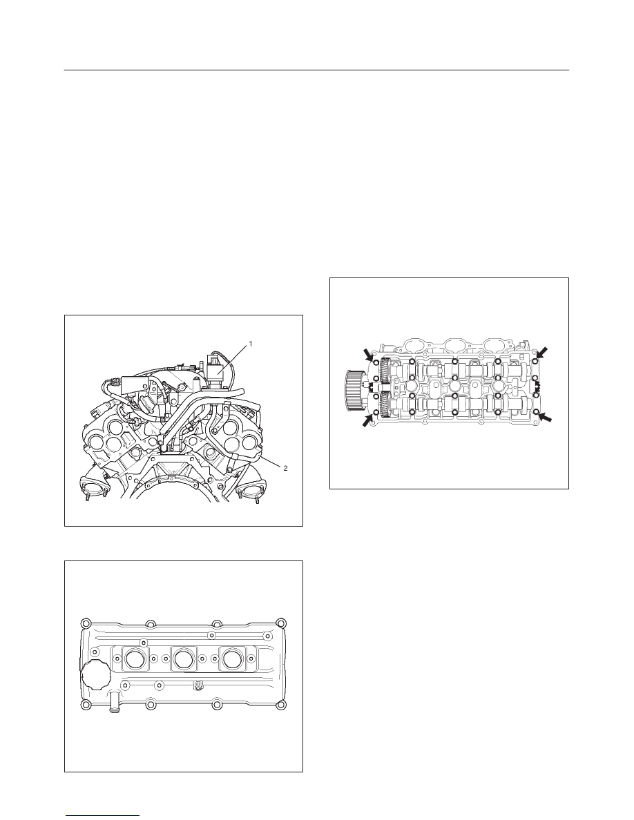
Cylinder Head Cover RH
Removal
1. Disconnect battery ground cable.
2. Disconnect ventilation hose from cylinder head cover.
3. Disconnect three ignition coil connectors from ignition
coils and remove harness bracket bolts on cylinder
head cover then remove ignition coil fixing bolts on
ignition coils and remove ignition coils.
4. Remove heater pipe fixing bolts from the bracket.
5. Disconnect fuel injector harness connector then
remove fuel injector harness bracket bolt.
6. Remove exhaust gas recirculation (EGR) pipe.
f
Remove flare nut from EGR valve.
f
Remove fixing bolt of EGR pipe bracket on rear end
cylinder head.
f
Remove two fixing bolt and nut on exhaust
manifold.
056RW001
7. Remove eight fixing bolts then the cylinder head
cover.
010RW002
Installation
1. Install cylinder head cover.
f
Clean the sealing surface of cylinder head and
cylinder head cover to remove oil and sealing
materials completely.
Apply sealant (TB-1207B or equivalent) of bead
diameter 2-3 mm at eight place of arched area of
camshaft bracket on front and rear sides.
f
The cylinder head cover must be installed within 5
minutes after sealant application to prevent
premature hardening of sealant.
f
Tighten bolts to the specified torque.
Torque : 9 N·m (80 lb in)
014RW019
2. Install exhaust gas recirculation pipe and tighten to
specified torque.
Torque:
Exhaust manifold side: 28 N·m (21 lb ft)
Flare nut: 44 N·m (33 lb ft)
Cylinder head side: 25 N·m (18 lb ft)
3. Tighten fuel injector harness bracket bolts to
specified torque then reconnect fuel injector harness
connector.
Torque : 7.8 N·m (5.7 lb ft)
4. Install heater pipe bolt to the specified torque.
Torque : 21 N·m (15 lb ft)
5. Connect ignition coil connector and tighten ignition
coil fixing bolts to specified torque.
Torque : 4 N·m (35 lb in)
6. Connect ventilation hose to cylinder head.
6A–22
ENGINE MECHANICAL (6VD1 3.2L)
Common Chamber
Removal
1. Disconnect battery ground cable.
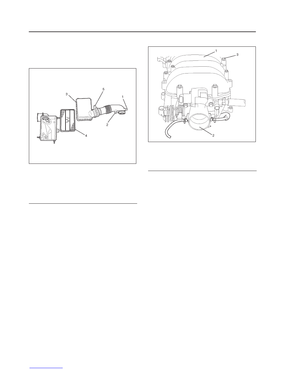
2. Remove air cleaner duct assembly.
130RW001
Legend
(1) Positive Crankcase Ventilation Hose Connector
(2) Intake Air Temperature Sensor
(3) Air Cleaner Duct Assembly
(4) Air Cleaner Element
(5) Air Flow Sensor
3. Disconnect accelerator pedal cable from throttle body
and cable bracket.
4. Disconnect vacuum booster hose from common
chamber.
5. Disconnect connector from manifold absolute
pressure sensor, idle air control valve, throttle
position sensor, solenoid valve, electric vacuum
sensing valve, and EGR valve.
6. Disconnect vacuum hose on canister VSV and
positive crankcase ventilation hose, fuel rail
assembly with pressure control valve bracket.
7. Remove ventilation hose from throttle valve and
intake duct and remove water hose.
8. Remove the four throttle body fixing bolts.
9. Remove exhaust gas recirculation valve assembly
fixing bolt and nut on common chamber and remove
EGR valve assembly.
10. Remove two bolts from common chamber rear side
for remove fuel hose bracket.
11. Remove common chamber four bolts and four nuts
then remove the common chamber.
025RW001
Legend
(1) Common Chamber
(2) Throttle Valve Assembly
(3) Bolt
Installation
1. Install common chamber and tighten bolts and nuts to
the specified torque.
Torque :
Bolt : 25 N·m (18 lb ft)
Nut : 25 N·m (18 lb ft)
2. Install fuel hose bracket and tighten bolts to specified
torque.
Torque : 10 N·m (89 lb in)
3. Install exhaust gas recirculation valve assembly and
tighten bolt and nut to the specified torque.
Torque : 25 N·m (18 lb ft)
4. Install throttle body and tighten bolts to the specified
torque.
Torque : 25 N·m (18 lb ft)
5. Install ventilating hose to throttle valve and intake
duct.
6. Connect vacuum hoses on canister VSV and positive
crankcase ventilation hose. Tighten bolts for fuel rail
assembly with pressure control valve bracket.
Torque : 25 N·m (18 lb ft)
7. Connect each connector without fail.
8. Connect vacuum booster hose.
9. Connect accelerator pedal cable.
6A–23
ENGINE MECHANICAL (6VD1 3.2L)
10. Install air cleaner duct assembly.
130RW001
Legend
(1) Positive Crankcase Ventilation Hose Connector
(2) Intake Air Temperature Sensor
(3) Air Cleaner Duct Assembly
(4) Air Cleaner Element.
(5) Air Flow Sensor
6A–24
ENGINE MECHANICAL (6VD1 3.2L)
Exhaust Manifold LH
Removal
1. Disconnect battery ground cable.
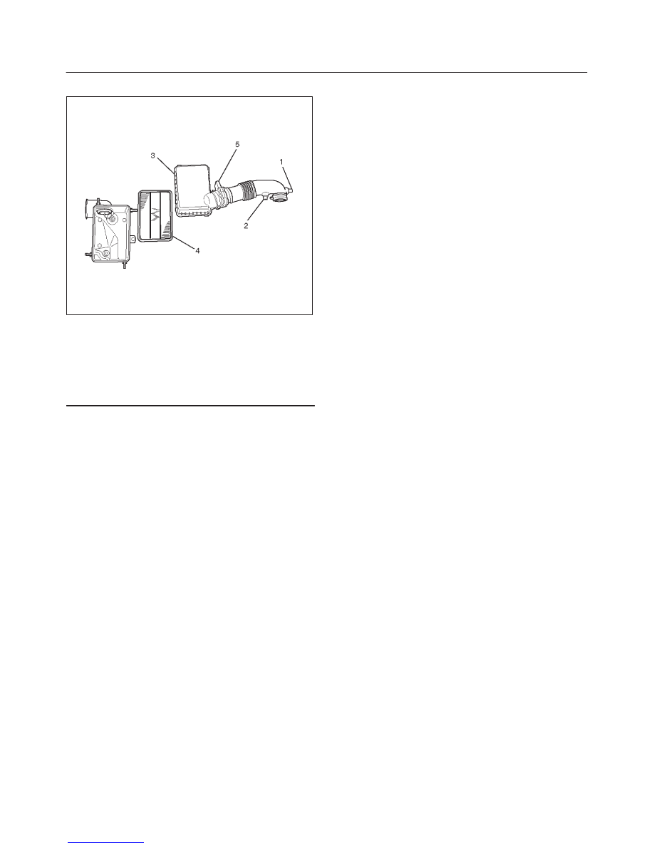
2. Remove air cleaner duct assembly.
130RW001
Legend
(1) Positive Crankcase Ventilation Hose Connector
(2) Intake Air Temperature Sensor
(3) Air Cleaner Duct Assembly
(4) Air Cleaner Element
(5) Air Flow Sensor
3. Disconnect O
2
sensor connector.
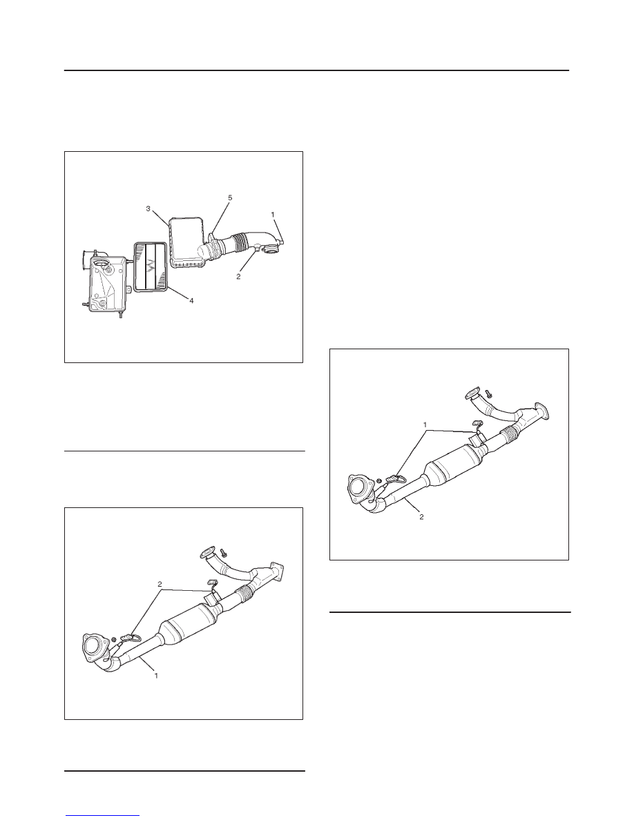
4. Remove exhaust front pipe three stud nuts from
exhaust side and two nuts from rear end of exhaust
front pipe.
035RW006
Legend
(1) Exhaust Front Pipe LH
(2) O
2
Sensor
5. Remove heat protector two fixing bolts then the heat
protector.
6. Remove a bolt on engine LH side for air conditioner
(A/C) compressor bracket and loosen two bolts for
A/C compressor then move A/C compressor to front
side.
7. Remove exhaust manifold eight fixing nuts and
remove exhaust manifold from the engine.
Installation
1. Install exhaust manifold and tighten exhaust manifold
fixing nuts to the specified torque with new nuts.
Torque: 57 N·m (42 lb ft)
2. Install heat protector.
3. Install exhaust front pipe and tighten three stud nuts
and two nuts to the specified torque.
Torque :
Stud nuts: 67 N·m (49 lb ft)
Nuts: 43 N·m (32 lb ft)
035RW016
Legend
(1) O
2
Sensor
(2) Exhaust Front Pipe LH
4. Set A/C compressor to normal position and tighten
two bolts and a bolt to the specified torque.
Torque : 40 N·m (30 lb ft)
5. Reconnect O
2
sensor connector.
6. Install air cleaner duct assembly.
Нет комментариевНе стесняйтесь поделиться с нами вашим ценным мнением.
Текст