Infiniti G35 (2008 year). Manual — part 10
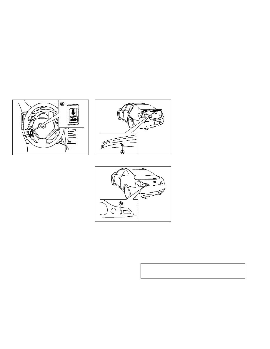
TRUNK LID RELEASE SWITCH
The trunk lid release switch
s
A
is located on the
instrument panel.
To open the trunk lid, push the release switch
down as illustrated. To close, push the trunk lid
down.
You can open the trunk lid with Intelligent Key.
(See “INTELLIGENT KEY SYSTEM” page 3-6 or
“REMOTE KEYLESS ENTRY SYSTEM” earlier in
this section.)
TRUNK OPEN REQUEST SWITCH
The trunk lid can be opened by pushing the
trunk open request switch when the Intelligent
Key is within the operating range of the trunk
lock/unlock function regardless of the inside
lock knob position. (See “INTELLIGENT KEY SYS-
TEM” earlier in this section.)
SPA2307
Sedan
SPA2304
Coupe
SPA2404
3-18
Pre-driving checks and adjustments
w
—
—
07/05/07—pattie
X
-------------------------------------------------------------------------------------------------------------------------------------------------------------
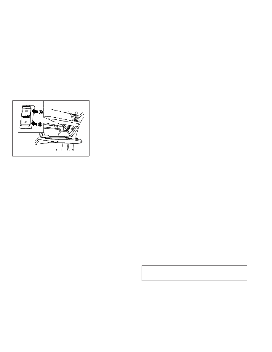
TRUNK RELEASE POWER CANCEL
SWITCH
When the switch located inside the glove box is
in the OFF position
s
A
, the power to the trunk
lid will be canceled and the trunk lid cannot be
opened by the trunk lid release switch, the
trunk open request switch with the Intelligent
Key carried with you or the TRUNK button on the
Intelligent Key.
When you have to leave the vehicle with a valet
and want to keep your belongings safe in the
glove box and the trunk, push this switch to OFF
and lock the glove box with the mechanical key.
Then leave the vehicle and the Intelligent Key
with the valet and keep the mechanical key with
you.
See “KEYS” earlier in this section.
To connect the power to the trunk lid, push the
switch to the ON
s
B
position.
SPA2308
Pre-driving checks and adjustments
3-19
w
—
—
07/05/07—pattie
X
-------------------------------------------------------------------------------------------------------------------------------------------------------------

INTERIOR TRUNK LID RELEASE
WARNING
Closely supervise children when they are
around cars to prevent them from playing and
becoming locked in the trunk where they could
be seriously injured. Keep the car locked, with
the trunk lid securely latched, when not in use,
and prevent children’s access to Intelligent
Keys.
The interior trunk lid release mechanism allows
opening of the trunk lid in the event that people
become locked inside the trunk or in the event
of the loss of electrical power such as a dis-
charged battery.
Releasing inside the trunk
To open the trunk lid from the inside, pull the
release handle
s
1
until the lock releases and
push up on the trunk lid. The release lever is
made of a material that glows in the dark after
a brief exposure to ambient light.
The handle is located on the back of the trunk
lid as illustrated.
Releasing from the rear seat
Sedan
You can also access the release handle through
the trunk pass-through (rear seat armrest). (See
“ARMREST” in the “1. Safety — Seats, seat belts
and supplemental restraint system” section.)
To open the trunk lid from the rear seat, pull the
release handle towards front of vehicle until the
lock releases.
Sedan
SPA2327
Coupe
SPA2402
3-20
Pre-driving checks and adjustments
w
—
—
07/05/07—pattie
X
-------------------------------------------------------------------------------------------------------------------------------------------------------------

Coupe
You can access the release handle by folding
the rear seat.
Pull the strap
s
1
, located at center bottom of
the seatback sideways, and then fold down the
seatback
s
2
.
To open the trunk lid from the rear seat, pull the
release handle towards front of vehicle until the
lock releases.
OPENING THE FUEL-FILLER DOOR
To open the fuel-filler door, unlock the fuel-filler
door by using one of the following operations,
then push the right side of the door (Sedan) or
push the left side of the door (Coupe).
● Push the door handle request switch with
the Intelligent Key carried with you.
● Push the UNLOCK button on the Intelligent
Key.
● Insert the mechanical key into the door lock
cylinder and turn it to the rear of the vehicle.
● Push the power door lock switch to the
UNLOCK position.
To lock, close the fuel-filler door securely and
lock all doors by operating the door handle
request switch, the LOCK button on the Intelli-
gent Key, the mechanical key or the power door
lock switch.
Coupe
SPA2122
Sedan
SPA2340
Coupe
SPA1562A
FUEL-FILLER DOOR
Pre-driving checks and adjustments
3-21
w
—
—
07/14/07—pattie
X
-------------------------------------------------------------------------------------------------------------------------------------------------------------
FUEL-FILLER CAP
WARNING
● Gasoline is extremely flammable and highly
explosive under certain conditions. You
could be burned or seriously injured if it is
misused or mishandled. Always stop engine
and do not smoke or allow open flames or
sparks near the vehicle when refueling.
● Do not attempt to top off the fuel tank after
the fuel pump nozzle shuts off automati-
cally. Continued refueling may cause fuel
overflow, resulting in fuel spray and possi-
bly a fire.
● Use only an original equipment type fuel-
filler cap as a replacement. It has a built-in
safety valve needed for proper operation of
the fuel system and emission control sys-
tem. An incorrect cap can result in a serious
malfunction and possible injury. It could
also cause the malfunction indicator light to
come on.
● Never pour fuel into the throttle body to at-
tempt to start your vehicle.
● Do not fill a portable fuel container in the
vehicle or trailer. Static electricity can cause
an explosion of flammable liquid, vapor or
gas in any vehicle or trailer. To reduce the
risk of serious injury or death when filling
portable fuel containers:
– Always place the container on the ground
when filling.
– Do not use electronic devices when filling.
– Keep the pump nozzle in contact with the
container while you are filling it.
– Use only approved portable fuel contain-
ers for flammable liquid.
CAUTION
● If fuel is spilled on the vehicle body, flush it
away with water to avoid paint damage.
● Tighten until the fuel-filler cap clicks. Failure
to tighten the fuel-filler cap properly may
cause the
malfunction indicator light
(MIL) to illuminate. If the
light illumi-
nates because the fuel-filler cap is loose or
missing, tighten or install the cap and con-
tinue to drive the vehicle. The
light
should turn off after a few driving trips. If the
light does not turn off after a few driv-
ing trips, have the vehicle inspected by an
INFINITI dealer.
3-22
Pre-driving checks and adjustments
w
—
—
07/05/07—pattie
X
-------------------------------------------------------------------------------------------------------------------------------------------------------------
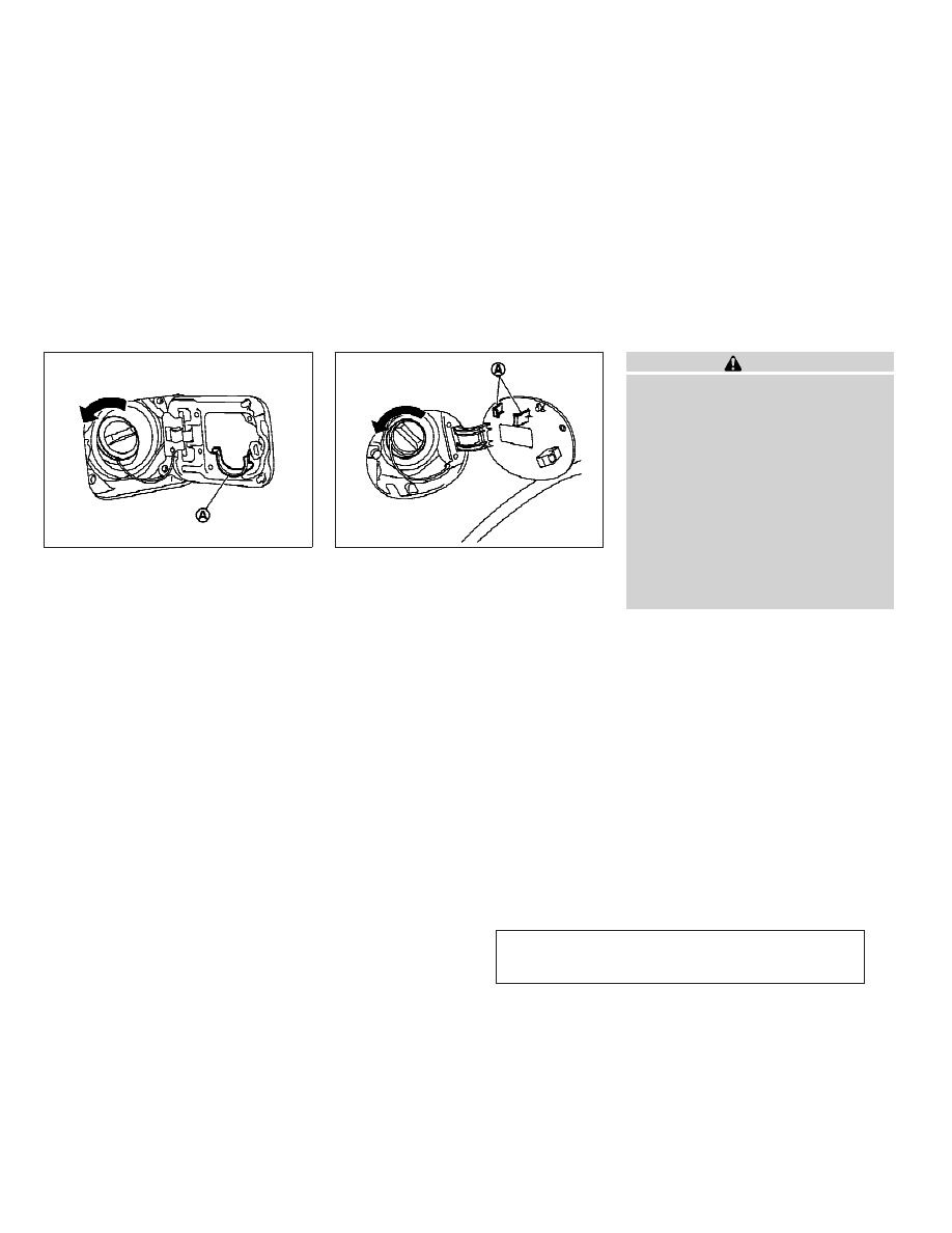
The fuel-filler cap is a ratcheting type. Turn the
cap counterclockwise to remove. To tighten,
turn the cap clockwise until ratcheting clicks
are heard.
Put the fuel-filler cap on the cap holder
s
A
while refueling.
WARNING
● Do not adjust the steering wheel while driv-
ing. You could lose control of your vehicle
and cause an accident.
● Do not adjust the steering wheel any closer
to you than is necessary for proper steering
operation and comfort. The driver’s air bag
inflates with great force. If you are unre-
strained, leaning forward, sitting sideways
or out of position in any way, you are at
greater risk of injury or death in a crash. You
may also receive serious or fatal injuries
from the air bag if you are up against it when
it inflates. Always sit back against the seat-
back and as far away as practical from the
steering wheel. Always use the seat belts.
Sedan
SPA2338
Coupe
SPA2403
TILTING TELESCOPIC STEERING COLUMN
Pre-driving checks and adjustments
3-23
w
—
—
07/05/07—pattie
X
-------------------------------------------------------------------------------------------------------------------------------------------------------------
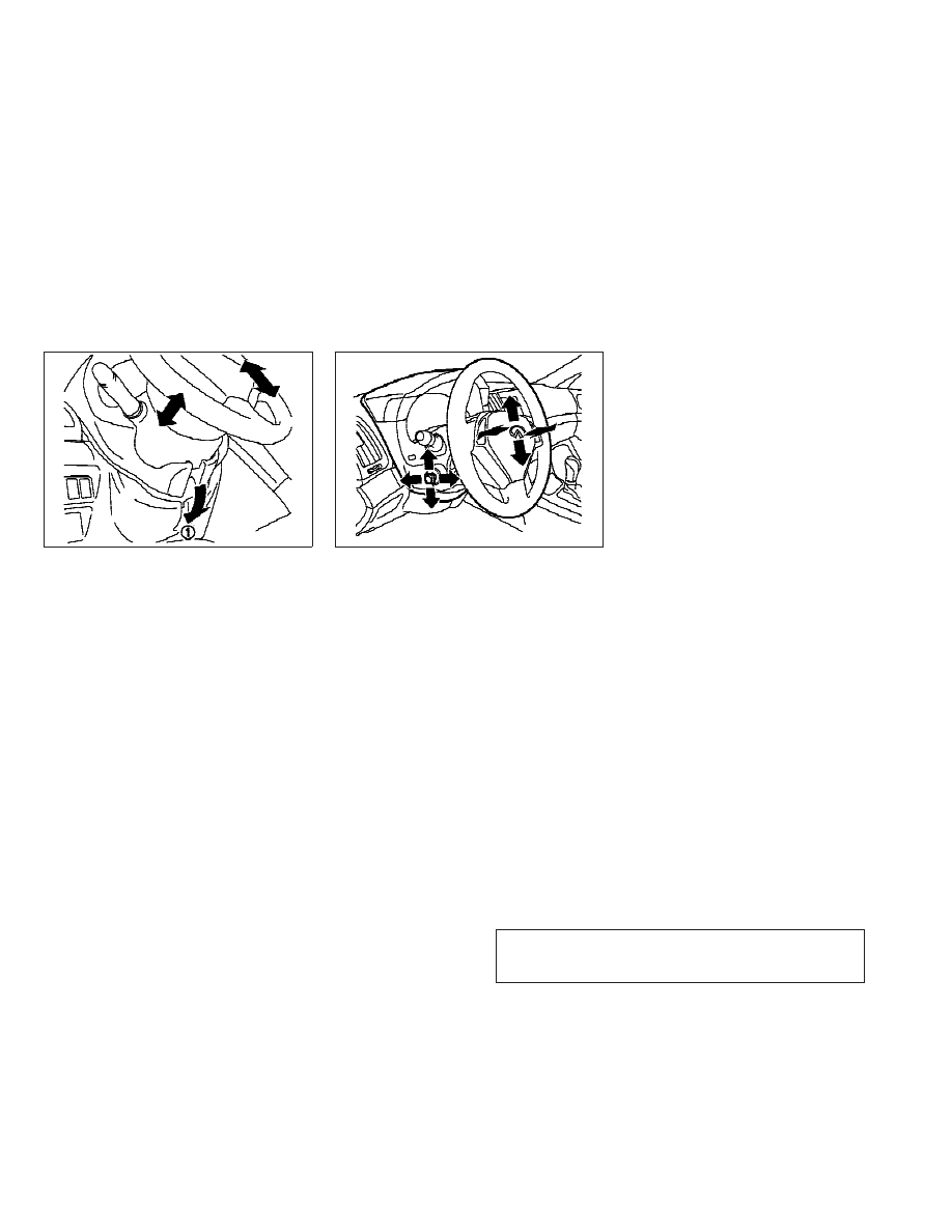
MANUAL OPERATION (if so equipped)
Tilt or telescopic operation
Pull the lock lever
s
1
down and adjust the
steering wheel up, down, forward or rearward to
the desired position.
Push the lock lever up securely to lock the
steering wheel in place.
ELECTRIC OPERATION (if so equipped)
Tilt or telescopic operation
Move the lever to adjust the steering wheel up
or down, forward or rearward to the desired
position.
Entry/Exit function operation (if so equipped)
The automatic drive positioner system will
make the steering wheel move up automatically
when the driver’s door is opened with the
ignition switch in the LOCK position. This lets
the driver get into and out of the seat more
easily.
For more information, see “AUTOMATIC DRIVE
POSITIONER” later in this section.
SPA2328
SPA2312
3-24
Pre-driving checks and adjustments
w
—
—
07/05/07—pattie
X
-------------------------------------------------------------------------------------------------------------------------------------------------------------
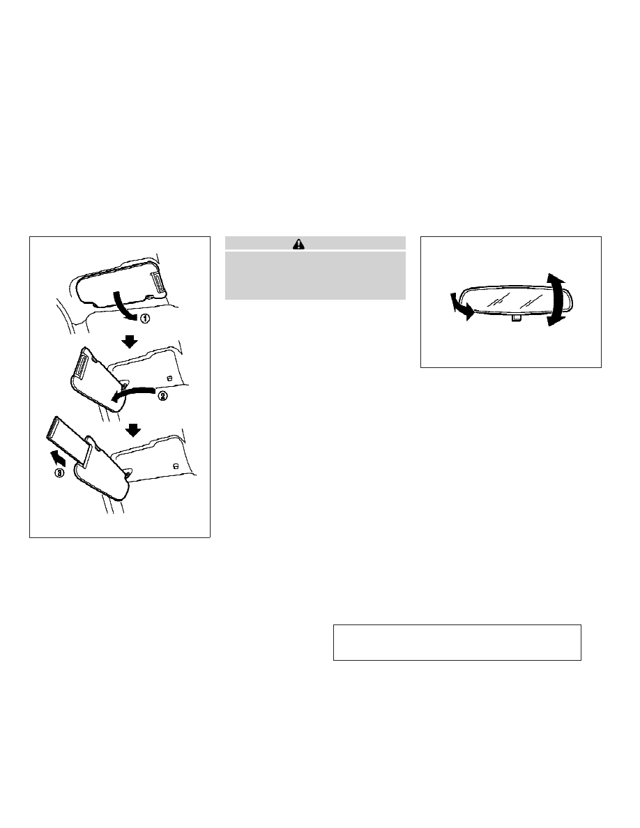
CAUTION
● Do not store the main sun visor before stor-
ing the extension sun visor.
● Do not pull the extension sun visor forcedly
downward.
1. To block out glare from the front, swing
down the main sun visor
s
1
.
2. To block glare from the side, remove the
main sun visor from the center mount and
swing it to the side
s
2
.
3. Draw out the extension sun visor
s
3
from
the main sun visor to block from further
glare.
INSIDE MIRROR
Adjust the height and the angle of the inside
mirror to the desired position.
SIC3451
SPA2343
SUN VISORS
MIRRORS
Pre-driving checks and adjustments
3-25
w
—
—
07/05/07—pattie
X
-------------------------------------------------------------------------------------------------------------------------------------------------------------

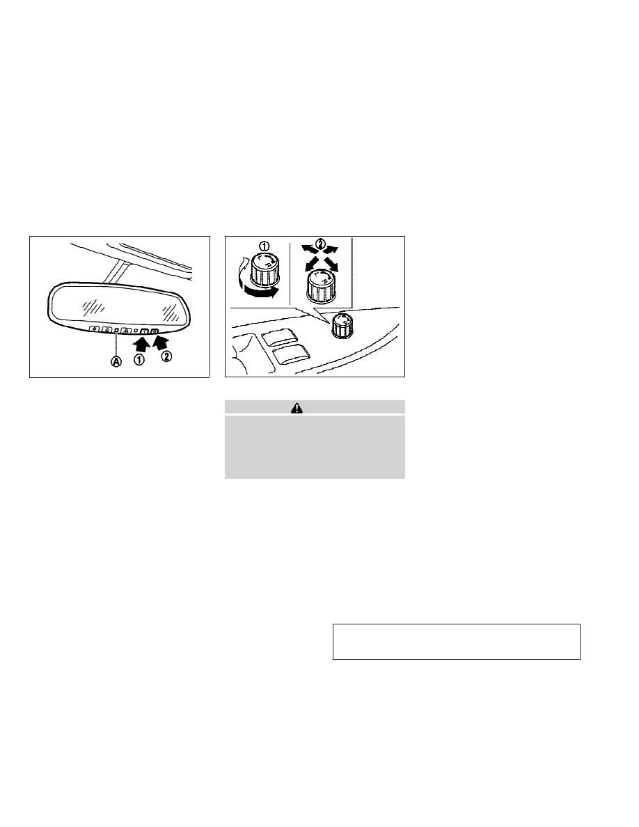
Manual anti-glare type
The night position
s
1
will reduce glare from the
headlights of vehicles behind you at night.
Use the day position
s
2
when driving in day-
light hours.
WARNING
Use the night position only when necessary,
because it reduces rear view clarity.
Automatic anti-glare type
Type A
The inside mirror is designed so that it auto-
matically changes reflection according to the
intensity of the headlights of the following
vehicle.
The anti-glare system will be automatically
turned on when you push the ignition switch to
the ON position.
When the system is turned on, the indicator
light
s
B
will illuminate and excessive glare from
the headlights of the vehicle behind you will be
reduced.
Push the
switch
s
A
to make the inside
rearview mirror operate normally and the indi-
cator light will turn off. Push the
switch
again to turn the system on.
Do not allow any object to cover the sensor
s
C
or
apply glass cleaner on it. Doing so will reduce
the sensitivity of the sensor, resulting in im-
proper operation.
For HomeLink
T Universal Transceiver (if so
equipped), see “HomeLink
T UNIVERSAL TRANS-
CEIVER” in the “2. Instruments and controls”
section.
SPA2143
SPA2253
Type A
3-26
Pre-driving checks and adjustments
w
—
—
08/10/07—pattie
X
-------------------------------------------------------------------------------------------------------------------------------------------------------------
Type B
The inside mirror is designed so that it auto
matically changes reflection according to the
intensity of the headlights of the following
vehicle.
When the inside mirror isin the
0|0 (AUTO)
position
s
1
, excessive glare from the head-
lights of the vehicle behind you will be reduced.
The AUTO indicator light
s
A
(green) will be on.
When the switch of the inside mirror is in the
0
s
0 (OFF) position
s
2
, the inside mirror will
operate normally.
OUTSIDE MIRRORS
WARNING
Objects viewed in the outside mirror on the
passenger side are closer than they appear. Be
careful when moving to the right. Using only
this mirror could cause an accident. Use the
inside mirror or glance over your shoulder to
properly judge distances to other objects.
Adjusting outside mirrors
The outside mirror control switch is located on
the armrest.
The outside mirror will operate only when the
ignition switch is in the ACC or ON position.
Turn the switch right or left to select the right or
left side mirror
s
1
, then adjust using the con-
trol switch
s
2
.
Defrosting outside mirrors (if so
equipped)
The outside mirrors will be heated when the
rear window defroster switch is operated.
SPA2157
Type B
SPA2319
Pre-driving checks and adjustments
3-27
w
—
—
08/10/07—pattie
X
-------------------------------------------------------------------------------------------------------------------------------------------------------------

Foldable outside mirrors
Fold the outside mirror by pushing it toward the
rear of the vehicle.
VANITY MIRROR
To use the front vanity mirror, pull down the sun
visor and pull up the cover.
SPA1829
Type A
SIC2064
Type B
SIC2555A
3-28
Pre-driving checks and adjustments
w
—
—
08/09/07—pattie
X
-------------------------------------------------------------------------------------------------------------------------------------------------------------
The automatic drive positioner system has three
features:
● Entry/exit function (Automatic Transmission
Sedan models)
● Seat synchronization function
● Memory storage
ENTRY/EXIT FUNCTION (Automatic
Transmission Sedan models)
This system is designed so that the driver’s seat
and steering column will automatically move
when the automatic transmission selector lever
is in the P (Park) position. This allows the driver
to get into and out of the driver’s seat more
easily. Note that the function is set to disabled
as the factory default setting.
The driver’s seat will slide backward and the
steering wheel will move up when the driver’s
door is opened with the ignition switch in the
LOCK position.
The driver’s seat and steering wheel will return
to the previous positions when one of the
following is operated:
● When the ignition switch is pushed to the
ACC position after the driver’s door is
closed.
● When the ignition switch is pushed to the
ON position.
The driver’s seat will not return to the previous
positions if the seat or steering adjusting
switch is operated when the seat is at the exit
position.
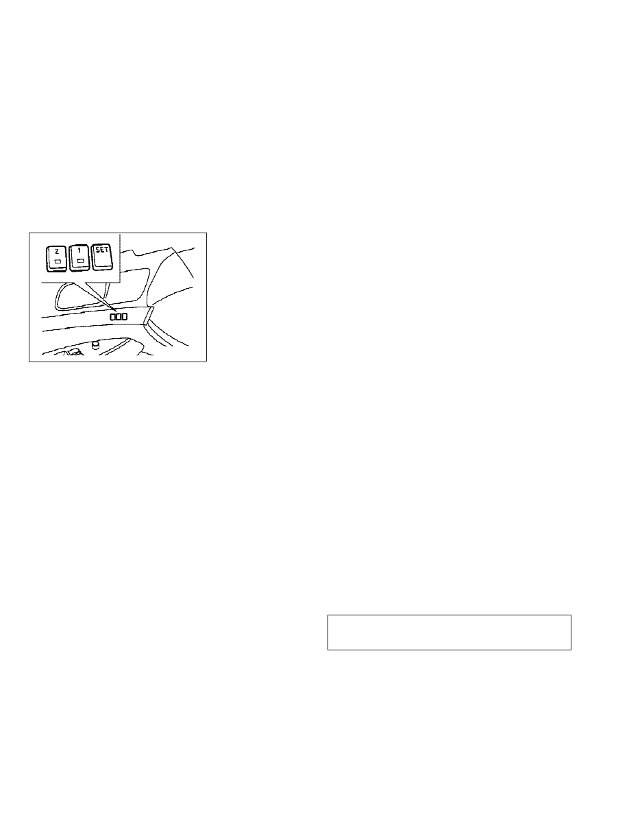
Cancel or activate entry/exit function
The selector lever must be in the P (Park)
position with the ignition switch in the OFF
position.
The entry/exit function can be activated or
canceled by pressing and holding the SET
switch for more than 10 seconds.
Activating or canceling the entry/exit function
using the SET switch also activates or cancels
the seat synchronization function.
The indicator lights on the memory switches (1
and 2) will blink once when the function is
canceled, and the indicator lights will blink
twice when the function is activated. Note that
the indicator lights may illuminate after 5 sec-
onds while holding the SET switch. This indi-
cates readiness for linking the Intelligent Key to
a stored memory position. Keep the SET switch
pressed for more than 10 seconds to turn on or
off the entry/exit function.
The entry/exit function can also be activated or
canceled if the “Lift Steering Wheel on Exit” key
or “Slide Driver Seat Back on Exit” key is turned
to ON or OFF in the “Comfort & Conv.” settings.
(See “VEHICLE INFORMATION AND SETTINGS” in
the “4. Monitor, climate, audio, phone and
voice recognition systems” section.)
Initialize entry/exit function
If the battery cable is disconnected, or if the
fuse opens, the entry/exit function will not work
though this function was set on before. In such
a case, after connecting the battery or replacing
with a new fuse, open and close the driver’s
door more than two times after the ignition
switch is turned from the ON position to the
LOCK position. The entry/exit function will be
activated.
AUTOMATIC DRIVE POSITIONER (if so
equipped)
Pre-driving checks and adjustments
3-29
w
—
—
08/09/07—pattie
X
-------------------------------------------------------------------------------------------------------------------------------------------------------------
SEAT SYNCHRONIZATION FUNCTION
The seat synchronization function automatically
adjusts the positions of the steering wheel and
outside mirrors when the seat is adjusted using
the power seat switches.
However, the steering wheel and outside mir-
rors will not move if the seat is adjusted over
the maximum thresholds. The system considers
that the steering wheel and outside mirror
adjustments are not necessary because the
seat may not be adjusted for the driving posi-
tion. Note that the function is set to disabled as
the factory default setting.
The seat synchronization function operates un-
der the following conditions:
● The ignition switch is in the ON position.
● The selector lever is in the P (Park) position
(Automatic Transmission models) or the
parking brake is applied (Manual Transmis-
sion models).
● The seatback is raised (Coupe).
If the outside mirrors or the steering wheel
reaches its maximum adjustment, the function
is automatically disabled. Restart the function
by selecting a previously stored seat memory
position using the memory switches (1 or 2). An
Intelligent Key that was previously linked to the
stored seat memory can also be used to restart
the function.
If a seat position was not previously stored in
the seat memory, restart the function by adjust-
ing the steering wheel and outside mirrors
manually for your best driving position and then
drive the vehicle above 4 MPH (7 km/h).
Cancel or activate seat
synchronization function
For Automatic Transmission models:
The selector lever must be in the P (Park)
position with the ignition switch in the OFF
position.
For Manual Transmission models:
The parking brake must be applied with the
ignition switch in the OFF position.
The seat synchronization function can be acti-
vated or canceled by pushing and holding the
SET switch for more than 10 seconds while the
ignition switch is in the OFF position.
Activating or canceling the seat synchronization
function using the SET switch also activates or
cancels the entry/exit function (Sedan).
The indicator lights on the memory switches (1
and 2) will blink once when the function is
canceled, and the indicator lights will blink
twice when the function is activated. Note that
the indicator lights may illuminate after 5 sec-
onds while holding the SET switch. This indi-
cates readiness for linking the Intelligent Key to
a stored memory position. Keep the SET switch
pushed for more than 10 seconds to turn on or
off the seat synchronization function.
For Automatic Transmission Sedan models, the
seat synchronization function can also be acti-
vated if both the “Lift Steering Wheel on Exit”
key and “Slide Driver Seat Back on Exit” key are
turned to ON or canceled if either the “Lift
Steering Wheel on Exit” key or “Slide Driver
Seat Back on Exit” key or both are turned to OFF
SPA2322
3-30
Pre-driving checks and adjustments
w
—
—
08/09/07—pattie
X
-------------------------------------------------------------------------------------------------------------------------------------------------------------

in the “Comfort & Conv.” settings. (See
“VEHICLE INFORMATION AND SETTINGS” in the
“4. Monitor, climate, audio, phone and voice
recognition systems” section.)
MEMORY STORAGE
Two positions for the driver’s seat, steering
column and outside mirrors can be stored in the
automatic drive positioner memory. Follow
these procedures to use the memory system.
1.
Automatic transmission models:
Move the selector lever to the P (Park)
position.
Manual transmission models:
Apply the parking brake.
2. Raise the seatback (Coupe).
3. Push the ignition switch to the ON posi-
tion.
4. Adjust the driver’s seat, steering column
and outside mirrors to the desired posi-
tions by manually operating each adjust-
ing switch. For additional information, see
“SEATS” in the “1. Safety — Seats, seat
belts and supplemental restraint system”
section and “TILTING TELESCOPIC STEER-
ING COLUMN” page 3-23 and “OUTSIDE
MIRRORS” earlier in this section.
5. Push the SET switch and, within 5 sec-
onds, push the memory switch (1 or 2)
fully for at least 1 second.
The indicator light for the pushed memory
switch will stay on for approximately 5 sec-
onds after pushing the switch.
If memory is stored in the same memory
switch, the previous memory will be deleted.
Linking Intelligent Key to a stored
memory position
The Intelligent Key can be linked to a stored
memory position with the following procedure.
1. Follow the steps for storing a memory
position.
2. While the indicator light for the memory
switch being set is illuminated for 5 sec-
onds, push the
button on the Intel-
ligent Key. If the indicator light blinks, the
Intelligent Key is linked to that memory
setting.
Push the ignition switch to the OFF position,
and then push the
button on the Intelli-
gent Key. The driver’s seat, steering wheel and
outside mirrors will move to the memorized
position.
Confirming memory storage
● Push the ignition switch to the ON position
and push the SET switch. If the main memory
has not been stored, the indicator light will
come on for approximately 0.5 second.
When the memory has stored in position, the
indicator light will stay on for approximately
5 seconds.
● If the battery cable is disconnected, or if the
fuse opens, the memory will be canceled. In
this case, reset the desired position using
the previous procedure.
● If optional Intelligent Keys are added to your
vehicle, the memory storage procedure to
switch 1 or 2 and linking Intelligent Key
procedure to a stored memory position
should be performed again for each Intelli-
gent Key. For additional Intelligent Key infor-
mation, see “KEYS” earlier in this section.
Selecting the memorized position
1.
Automatic transmission models:
Move the selector lever to the P (Park)
position.
Manual transmission models:
Apply the parking brake.
Pre-driving checks and adjustments
3-31
w
—
—
08/09/07—pattie
X
-------------------------------------------------------------------------------------------------------------------------------------------------------------
2. Raise the seatback (Coupe).
3. Use one of the following methods to move
the driver’s seat, the outside mirrors and
the steering wheel.
● Push the ignition switch to the ON position
and push the memory switch (1 or 2) fully for
at least 1 second.
● Within 45 seconds of opening the driver’s
door, push the memory switch (1 or 2) fully
for at least 1 second.
The driver’s seat, steering column and out-
side mirrors will move to the memorized
position with the indicator light flashing,
and then the light will stay on for approxi-
mately 5 seconds.
For manual transmission models, the memory
positions can be selected even when the engine
is running. In this case, move the shift lever to
the N (Neutral) position and apply the parking
brake. Then, perform step 2.
SYSTEM OPERATION
The automatic drive positioner system will not
work or will stop operating under the following
conditions:
● When the vehicle speed is above 4 MPH
(7 km/h).
● When the adjusting switch for the driver’s
seat and steering column is turned on while
the automatic drive positioner is operating.
● When the memory switch 1 or 2 is not
pushed for at least 1 second.
● When the seat, steering column and outside
mirrors have already been moved to the
memorized position.
● When no position is stored in the memory
switch.
● When the parking brake is released (MT
models).
● When the speed is above 4 MPH (7 km/h)
while the parking brake is applied (MT mod-
els).
To restart the drive positioner system, move
the parking brake to off and on.
● When the engine is started while moving the
automatic drive positioner.
● When the AT selector lever is moved from the
P (Park) position to any other position. (How-
ever, it will not be canceled if the switch is
pushed while the seat and steering column
are returning to the previous positions
(entry/exit function).)
● When the driver’s door remains open for
more than 45 seconds and the ignition
switch is not in the ON position.
● When the seatback is folded (Coupe).
● While the walk-in function operates (Coupe).
● The seat synchronization function is auto-
matically disabled if the outside mirrors or
steering wheel reaches its maximum adjust-
ment.
● The seat synchronization function will not
move if the seat is adjusted over one of the
following maximum thresholds:
– Seat sliding: 3.0 in (76 mm)
– Seatback reclining: 9.1 degrees
– Seat lifter (rear side): 0.8 in (20 mm)
3-32
Pre-driving checks and adjustments
w
—
—
08/09/07—pattie
X
-------------------------------------------------------------------------------------------------------------------------------------------------------------
Pre-driving checks and adjustments
3-33
w
—
—
07/05/07—pattie
X
-------------------------------------------------------------------------------------------------------------------------------------------------------------
Нет комментариевНе стесняйтесь поделиться с нами вашим ценным мнением.
Текст