Infiniti G20 (P11). Manual — part 210
6
CHECK SHIELD CIRCUIT
1. Turn ignition switch “OFF”.
2. Disconnect joint connector-1.
3. Check the following.
I
Continuity between joint connector-1 terminal 2 and ground
Refer to Wiring Diagram.
I
Joint connector-1
(Refer to EL-274, “HARNESS LAYOUT”.)
Continuity should exist.
4. Also check harness for short to power.
5. Then reconnect joint connector-1.
OK or NG
OK
©
GO TO 7.
NG
©
Repair open circuit or short to power in harness or connectors.
7
CHECK INTERMITTENT INCIDENT
Perform “TROUBLE DIAGNOSIS FOR INTERMITTENT INCIDENT”, EC-146.
©
INSPECTION END
SEF662Y
Component Inspection
NCEC0161
HEATED OXYGEN SENSOR 2 (REAR)
NCEC0161S01
With CONSULT-II
1)
Start engine and drive vehicle at a speed of more than 70 km/h
(43 MPH) for 2 consecutive minutes..
2)
Stop vehicle with engine running.
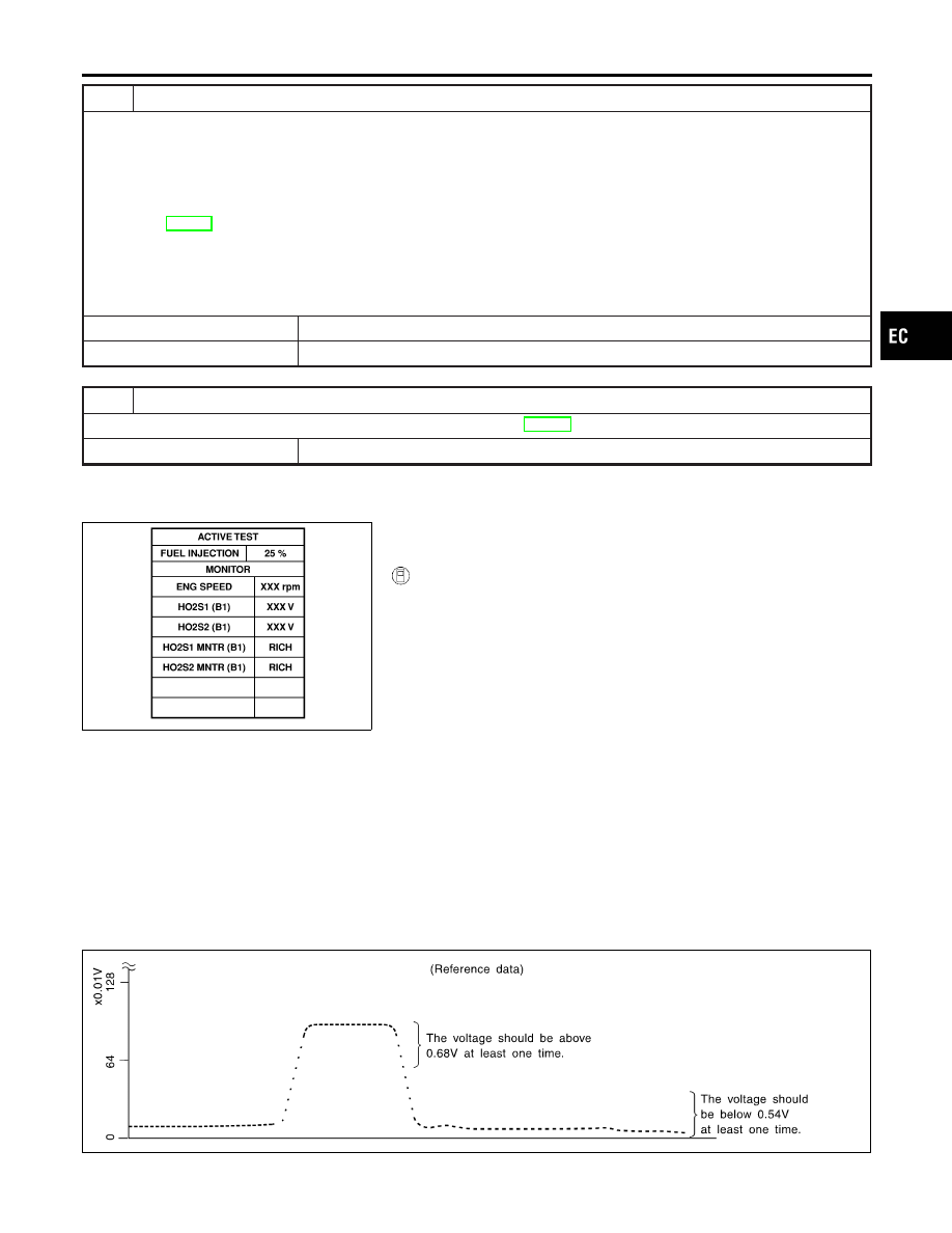
3)
Select “FUEL INJECTION” in “ACTIVE TEST” mode, and
select “HO2S2 (B1)” as the monitor item with CONSULT-II.
4)
Check “HO2S2 (B1)” at idle speed when adjusting “FUEL
INJECTION” to
±
25%.
“HO2S2 (B1)” should be above 0.68V at least once when
the “FUEL INJECTION” is +25%.
“HO2S2 (B1)” should be below 0.54V at least once when
the “FUEL INJECTION” is −25%.
CAUTION:
I
Discard any heated oxygen sensor which has been
dropped from a height of more than 0.5 m (19.7 in) onto a
hard surface such as a concrete floor; use a new one.
I
Before installing new oxygen sensor, clean exhaust sys-
tem threads using Oxygen Sensor Thread Cleaner tool
J-43897-18 or J-43897-12 and approved anti-seize lubri-
cant.
SEF244Y
GI
MA
EM
LC
FE
CL
MT
AT
AX
SU
BR
ST
RS
BT
HA
SC
EL
IDX
DTC P0138 HEATED OXYGEN SENSOR 2 (REAR) (MAX. VOLTAGE
MONITORING)
Diagnostic Procedure (Cont’d)
EC-251
SEF032X
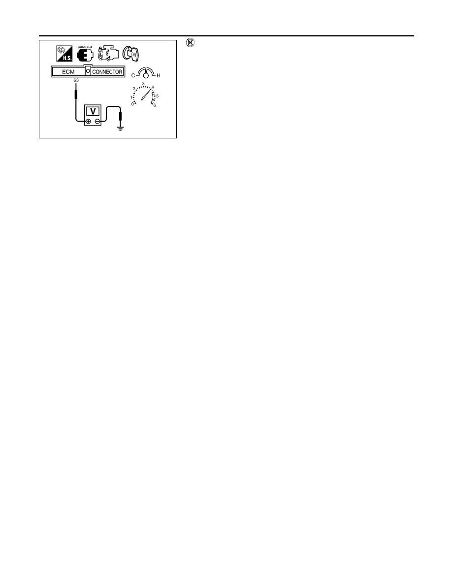
Without CONSULT-II
1)
Start engine and drive vehicle at a speed of 70 km/h (43 MPH)
for 2 consecutive minutes.
2)
Stop vehicle with engine running.
3)
Set voltmeter probes between ECM terminals 63 [Heated oxy-
gen sensor 2 (rear) signal] and engine ground.
4)
Check the voltage when revving up to 4,000 rpm under no load
at least 10 times.
(Depress and release accelerator pedal as soon as possible.)
The voltage should be above 0.68V at least once.
If the voltage is above 0.68V at step 4, step 5 is not nec-
essary.
5)
Check the voltage when revving up to 6,000 rpm under no
load. Or keep vehicle at idling for 10 minutes, then check the
voltage. Or check the voltage when coasting from 80 km/h (50
MPH) in 3rd gear position (M/T), D position with “OD” OFF
(A/T).
The voltage should be below 0.54V at least once.
CAUTION:
I
Discard any heated oxygen sensor which has been
dropped from a height of more than 0.5 m (19.7 in) onto a
hard surface such as a concrete floor; use a new one.
I
Before installing new oxygen sensor, clean exhaust sys-
tem threads using Oxygen Sensor Thread Cleaner tool
J-43897-18 or J-43897-12 and approved anti-seize lubri-
cant.
DTC P0138 HEATED OXYGEN SENSOR 2 (REAR) (MAX. VOLTAGE
MONITORING)
Component Inspection (Cont’d)
EC-252
SEF327R
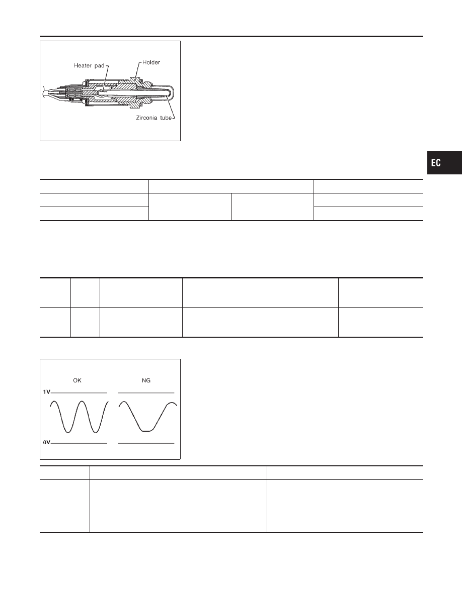
Component Description
NCEC0162
The heated oxygen sensor 2 (rear), after three way catalyst, moni-
tors the oxygen level in the exhaust gas.
Even if switching characteristics of the heated oxygen sensor 1
(front) are shifted, the air fuel ratio is controlled to stoichiometric,
by the signal from the heated oxygen sensor 2 (rear).
This sensor is made of ceramic zirconia. The zirconia generates
voltage from approximately 1V in richer conditions to 0V in leaner
conditions.
Under normal conditions the heated oxygen sensor 2 (rear) is not
used for engine control operation.
CONSULT-II Reference Value in Data Monitor
Mode
NCEC0163
Specification data are reference values.
MONITOR ITEM
CONDITION
SPECIFICATION
HO2S2 (B1)
I
Engine: After warming
up
Revving engine from idle
to 3,000 rpm
0 - 0.3V
+,
Approx. 0.6 - 1.0V
HO2S2 MNTR (B1)
LEAN
+,
RICH
ECM Terminals and Reference Value
NCEC0164
Specification data are reference values and are measured between each terminal and ground.
CAUTION:
Do not use ECM ground terminals when measuring input/output voltage. Doing so may result in dam-
age to the ECM’s transistor. Use a ground other than ECM terminals, such as the ground.
TERMI-
NAL
NO.
WIRE
COLOR
ITEM
CONDITION
DATA (DC Voltage)
63
W
Heated oxygen sensor 2
(rear)
[Engine is running]
I
After warming up to normal operating temperature
and revving engine from idle to 2,000 rpm
0 - Approximately 1.0V
SEF302U
On Board Diagnosis Logic
NCEC0165
The heated oxygen sensor 2 (rear) has a much longer switching
time between rich and lean than the heated oxygen sensor 1
(front). The oxygen storage capacity before the three way catalyst
causes the longer switching time. To judge the malfunctions of
heated oxygen sensor 2 (rear), ECM monitors whether the switch-
ing response of the sensor’s voltage is faster than specified during
various driving conditions such as fuel-cut.
DTC No.
Malfunction is detected when ...
Check Items (Possible Cause)
P0139
I
It takes more than the specified time for the sensor to
respond between rich and lean.
I
Harness or connectors
(The sensor circuit is open or shorted.)
I
Heated oxygen sensor 2 (rear)
I
Fuel pressure
I
Injectors
I
Intake air leaks
GI
MA
EM
LC
FE
CL
MT
AT
AX
SU
BR
ST
RS
BT
HA
SC
EL
IDX
DTC P0139 HEATED OXYGEN SENSOR 2 (REAR) (RESPONSE MONITORING)
Component Description
EC-253
SEF666Y
DTC Confirmation Procedure
NCEC0166
SEF667Y
SEF668Y
NOTE:
If “DTC Confirmation Procedure” has been previously conducted,
always turn ignition switch “OFF” and wait at least 10 seconds
before conducting the next test.
TESTING CONDITION:
Open engine hood before conducting following procedure.
With CONSULT-II
1)
Start engine and warm it up to normal operating temperature.
2)
Turn ignition switch “OFF” and wait at least 10 seconds.
3)
Turn ignition switch “ON”.
4)
Select “DATA MONITOR” mode with CONSULT-II.
5)
Make sure that “COOLAN TEMP/S” indicates more than 70°C
(158°F).
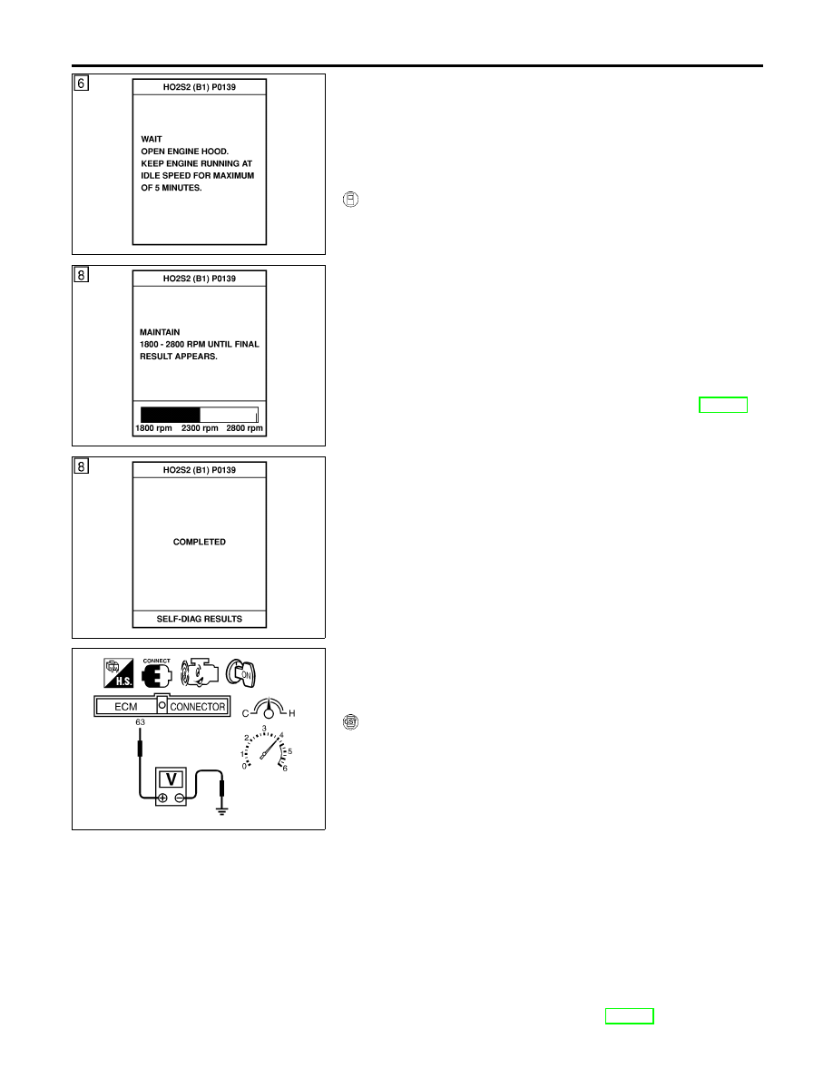
6)
Select “HO2S2 (B1) P0139” of “HO2S2” in “DTC WORK SUP-
PORT” mode with CONSULT-II.
7)
Start engine and follow the instruction of CONSULT-II.
8)
Make sure that “OK” is displayed after touching “SELF-DIAG
RESULTS”.
If NG is displayed, refer to “Diagnostic Procedure”, EC-256.
If “CANNOT BE DIAGNOSED” is displayed, perform the fol-
lowing.
a)
Stop engine and cool down until “COOLAN TEMP/S” indicates
less than 70°C (158°F).
b)
Turn ignition switch “ON”.
c)
Select “DATA MONITOR” mode with CONSULT-II.
d)
Start engine.
e)
Return to step 6 again when the “COOLAN TEMP/S” reaches
to 70°C (158°F).
SEF032X
Overall Function Check
NCEC0167
Use this procedure to check the overall function of the heated oxy-
gen sensor 2 (rear) circuit. During this check, a 1st trip DTC might
not be confirmed.
With GST
1)
Start engine and drive vehicle at a speed of more than 70 km/h
(43 MPH) for 2 consecutive minutes.
2)
Stop vehicle with engine running.
3)
Set voltmeter probes between ECM terminals 63 [Heated oxy-
gen sensor 2 (rear) signal] and engine ground.
4)
Check the voltage when revving up to 4,000 rpm under no load
at least 10 times.
(Depress and release accelerator pedal as soon as possible.)
The voltage should change at more than 0.06V for 1 sec-
ond during this procedure.
If the voltage can be confirmed in step 4, step 5 is not
necessary.
5)
Keep vehicle at idling for 10 minutes, then check the voltage.
Or check the voltage when coasting from 80 km/h (50 MPH)
in 3rd gear position (M/T), D position with “OD” OFF (A/T).
The voltage should change at more than 0.06V for 1 sec-
ond during this procedure.
6)
If NG, go to “Diagnostic Procedure”, EC-256.
DTC P0139 HEATED OXYGEN SENSOR 2 (REAR) (RESPONSE MONITORING)
DTC Confirmation Procedure
EC-254
Нет комментариевНе стесняйтесь поделиться с нами вашим ценным мнением.
Текст