Infiniti G20 (P11). Manual — part 214
Description
NCEC0180
SYSTEM DESCRIPTION
NCEC0180S01
Sensor
Input Signal to ECM
ECM func-
tion
Actuator
Camshaft position sensor
Engine speed
Heated
oxygen
sensor 2
heater
(rear) con-
trol
Heated oxygen sensor 2 heater
(rear)
The ECM performs ON/OFF control of the heated oxygen sensor 2 heater (rear) corresponding to the engine
speed.
OPERATION
NCEC0180S02
Engine speed rpm
Heated oxygen sensor 2 heater (rear)
Above 3,600
OFF
Below 3,600
ON
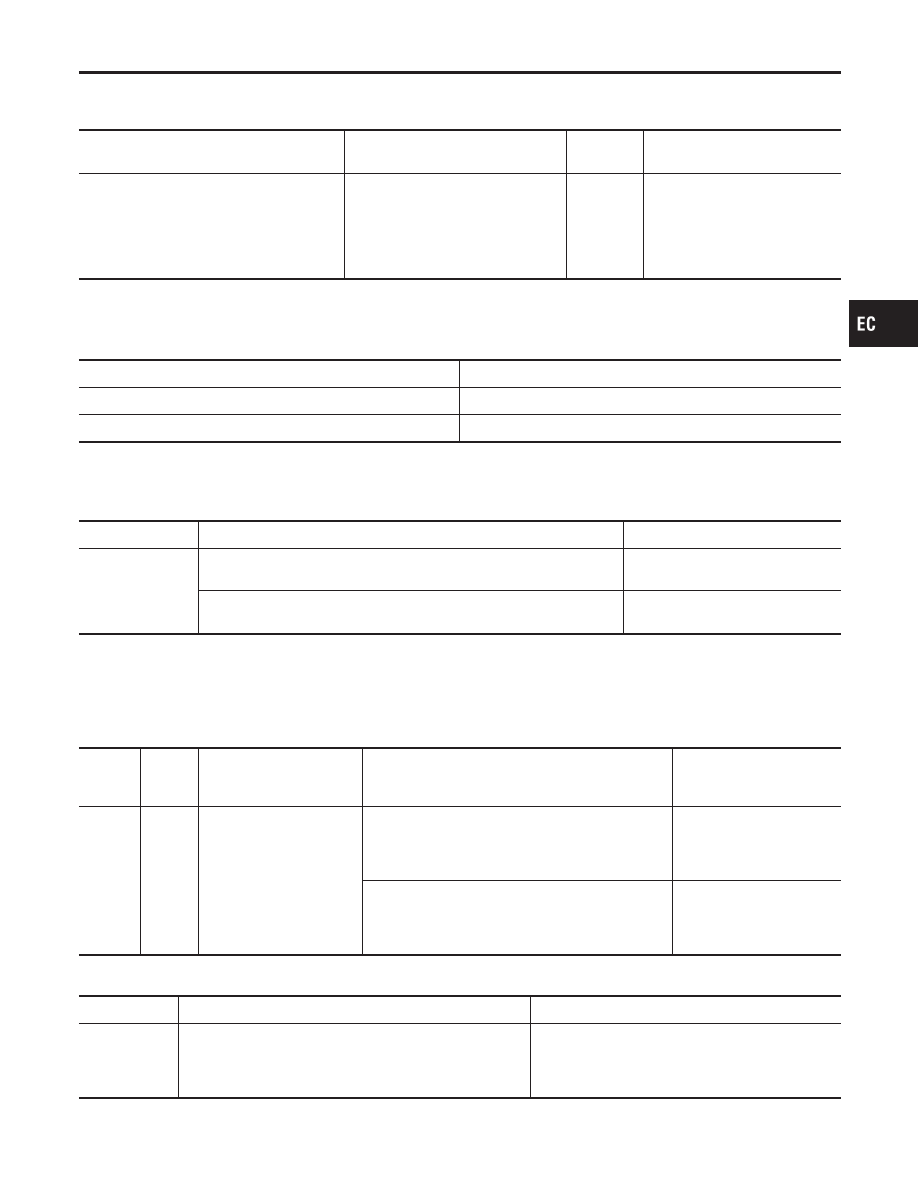
CONSULT-II Reference Value in Data Monitor
Mode
NCEC0181
Specification data are reference values.
MONITOR ITEM
CONDITION
SPECIFICATION
HO2S2 HTR (B1)
I
Ignition switch: ON (Engine stopped)
I
Engine speed: Above 3,600 rpm
OFF
I
Engine speed: Below 3,600 rpm [After driving for 2 minutes at a
speed of 70 km/h (43 MPH) or more]
ON
ECM Terminals and Reference Value
NCEC0182
Specification data are reference values and are measured between each terminal and ground.
CAUTION:
Do not use ECM ground terminals when measuring input/output voltage. Doing so may result in dam-
age to the ECM’s transistor. Use a ground other than ECM terminals, such as the ground.
TERMI-
NAL
NO.
WIRE
COLOR
ITEM
CONDITION
DATA (DC Voltage)
3
R/Y
Heated oxygen sensor 2
heater (rear)
[Engine is running]
I
Engine speed is below 3,600 rpm
I
After driving for 2 minutes at a speed of 70 km/h
(43 MPH) or more
0 - 1.0V
[Ignition switch “ON”]
I
Engine stopped
[Engine is running]
I
Engine speed is above 3,600 rpm
BATTERY VOLTAGE
(11 - 14V)
On Board Diagnosis Logic
NCEC0183
DTC No.
Malfunction is detected when ...
Check Items (Possible Cause)
P0141
I
The current amperage in the heated oxygen sensor 2
heater (rear) circuit is out of the normal range.
[An improper voltage drop signal is sent to ECM through
the heated oxygen sensor 2 heater (rear).]
I
Harness or connectors
[The heated oxygen sensor 2 heater (rear) circuit
is open or shorted.]
I
Heated oxygen sensor 2 heater (rear)
GI
MA
EM
LC
FE
CL
MT
AT
AX
SU
BR
ST
RS
BT
HA
SC
EL
IDX
DTC P0141 HEATED OXYGEN SENSOR 2 HEATER (REAR)
Description
EC-267
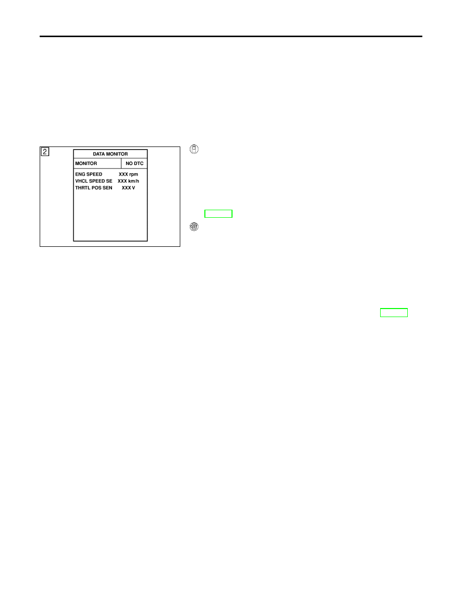
DTC Confirmation Procedure
NCEC0184
NOTE:
If “DTC Confirmation Procedure ” has been previously conducted,
always turn ignition switch “OFF” and wait at least 10 seconds
before conducting the next test.
TESTING CONDITION:
Before performing the following procedure, confirm that bat-
tery voltage is in between 10.5V and 16V at idle.
SEF175Y
With CONSULT-II
1)
Turn ignition switch “ON” and select “DATA MONITOR” mode
with CONSULT-II.
2)
Start engine and drive vehicle at a speed of more than 70 km/h
(43 MPH) for 2 consecutive minutes.
3)
Stop vehicle and let engine idle for at least 6 seconds.
4)
If 1st trip DTC is detected, go to “Diagnostic Procedure”,
EC-270.
With GST
1)
Start engine and drive vehicle at a speed of more than 70 km/h
(43 MPH) for 2 consecutive minutes.
2)
Stop vehicle and let engine idle for at least 6 seconds.
3)
Turn ignition switch “OFF” and wait at least 10 seconds.
4)
Start engine and drive vehicle at a speed of more than 70 km/h
(43 MPH) for 2 consecutive minutes.
5)
Stop vehicle and let engine idle for at least 6 seconds.
6)
Select “MODE 3” with GST.
7)
If DTC is detected, go to “Diagnostic Procedure”, EC-270.
When using GST, “DTC Confirmation Procedure” should be
performed twice as much as when using CONSULT-II because
GST cannot display MODE 7 (1st trip DTC) concerning this
diagnosis. Therefore, using CONSULT-II is recommended.
DTC P0141 HEATED OXYGEN SENSOR 2 HEATER (REAR)
DTC Confirmation Procedure
EC-268
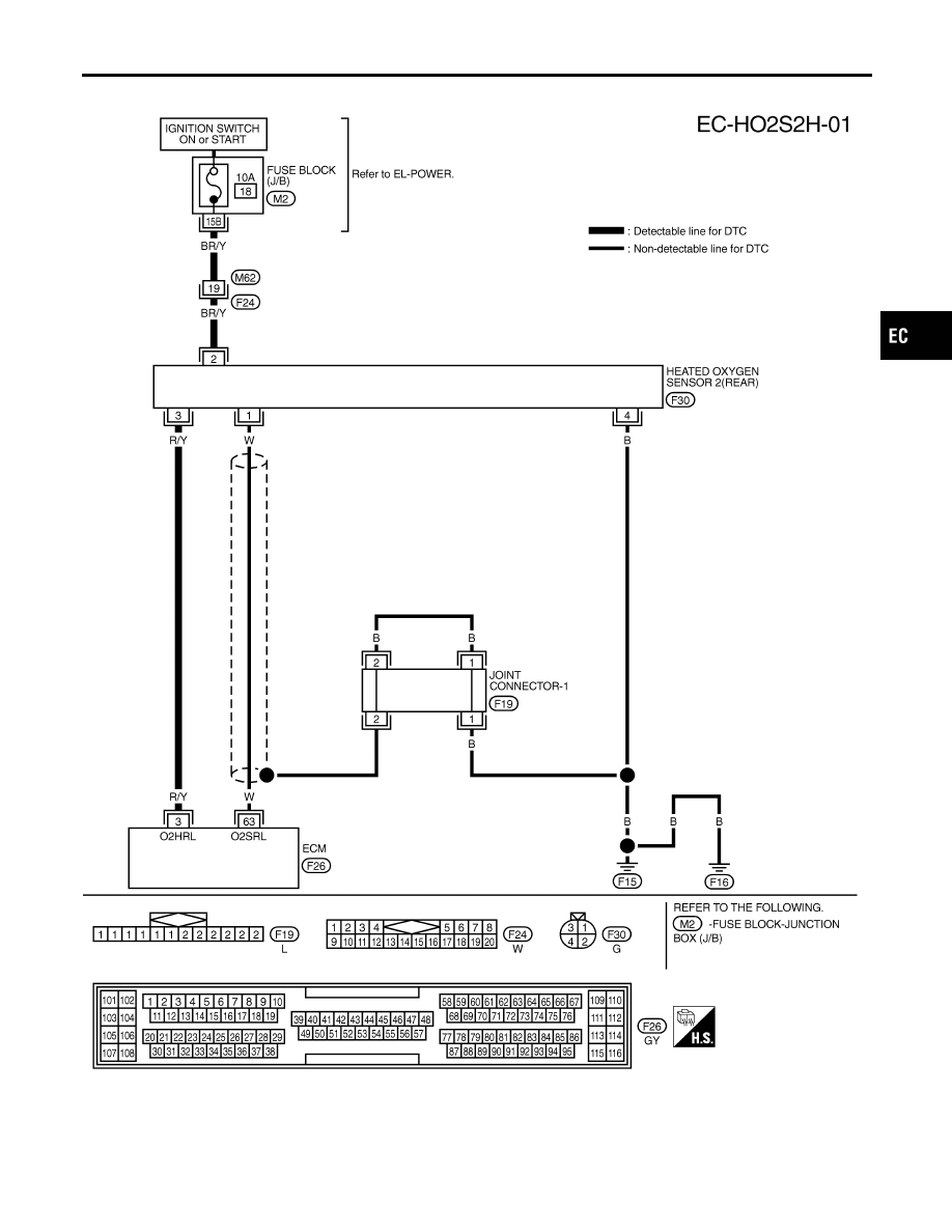
Wiring Diagram
NCEC0185
TEC840
GI
MA
EM
LC
FE
CL
MT
AT
AX
SU
BR
ST
RS
BT
HA
SC
EL
IDX
DTC P0141 HEATED OXYGEN SENSOR 2 HEATER (REAR)
Wiring Diagram
EC-269
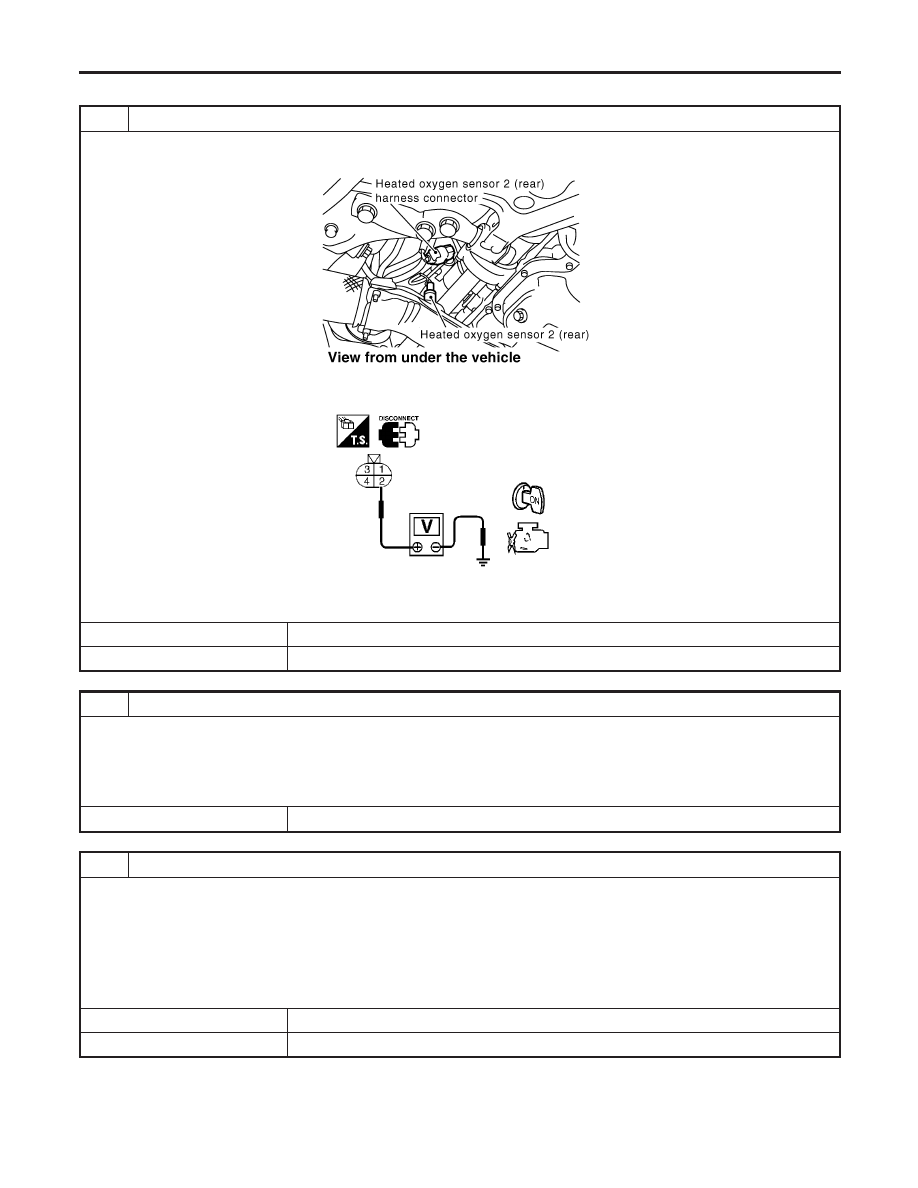
Diagnostic Procedure
NCEC0186
1
CHECK POWER SUPPLY
1. Turn ignition switch “OFF”.
2. Disconnect heated oxygen sensor 2 (rear) harness connector.
SEF918Z
3. Turn ignition switch “ON”.
4. Check voltage between HO2S2 terminal 2 and ground.
SEF218W
Voltage: Battery voltage
OK or NG
OK
©
GO TO 3.
NG
©
GO TO 2.
2
DETECT MALFUNCTIONING PART
Check the following.
I
Harness connectors M62, F24
I
Fuse block (J/B) connector M2
I
10A fuse
I
Harness for open or short between heated oxygen sensor 2 (rear) and fuse
©
Repair harness or connectors.
3
CHECK OUTPUT SIGNAL CIRCUIT
1. Turn ignition switch “OFF”.
2. Disconnect ECM harness connector.
3. Check harness continuity between HO2S2 terminal 3 and ECM terminal 3.
Refer to Wiring Diagram.
Continuity should exist.
4. Also check harness for short to ground and short to power.
OK or NG
OK
©
GO TO 4.
NG
©
Repair open circuit or short to ground or short to power in harness or connectors.
DTC P0141 HEATED OXYGEN SENSOR 2 HEATER (REAR)
Diagnostic Procedure
EC-270
Нет комментариевНе стесняйтесь поделиться с нами вашим ценным мнением.
Текст