Infiniti G20 (P11). Manual — part 140
Removal and Installation
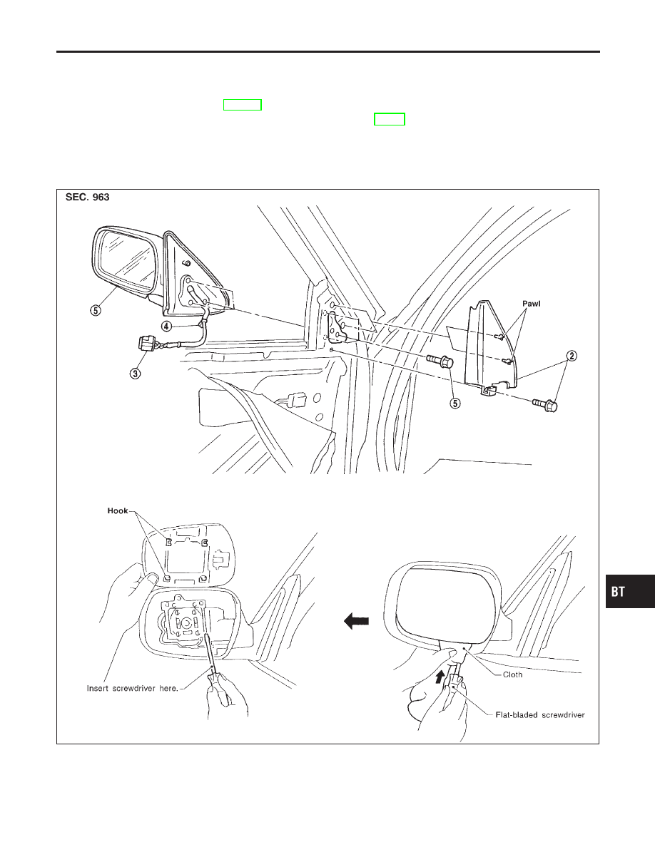
NCBT0020
CAUTION:
Be careful not to scratch door rearview mirror body.
★
For Wiring Diagram, refer to EL-143, “Wiring Diagram — MIRROR —”.
1. Remove front door trim. Refer to “DOOR TRIM” for details, BT-29.
2. Remove bolt securing inner cover, then remove inner cover.
3. Disconnect door mirror harness connector.
4. Remove door mirror harness clip.
5. Remove bolts securing door mirror, then remove door mirror assembly.
SBT418-A
GI
MA
EM
LC
EC
FE
CL
MT
AT
AX
SU
BR
ST
RS
HA
SC
EL
IDX
DOOR MIRROR
Removal and Installation
BT-55
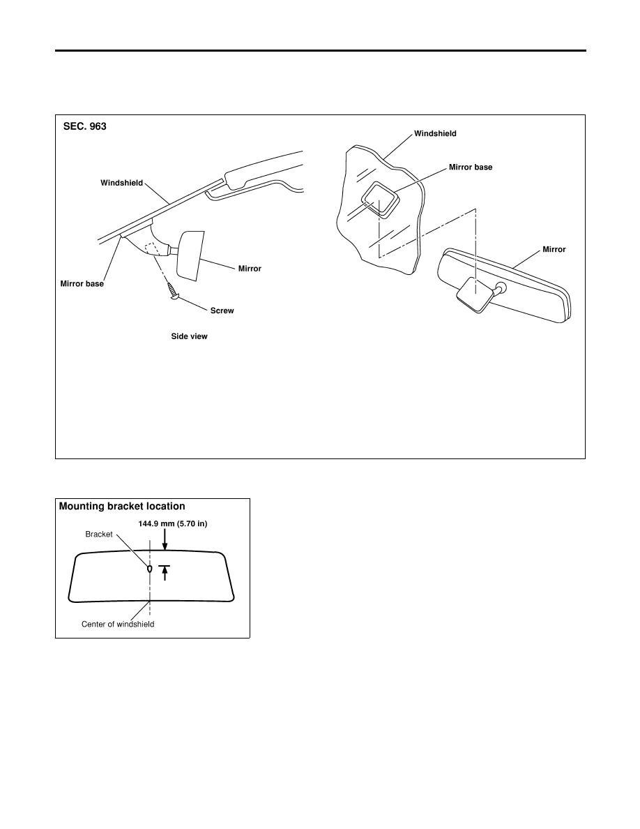
Removal and Installation
NCBT0029
REMOVAL
NCBT0029S01
Remove screw securing mirror assembly to mirror base as shown
in the figure.
SBT859
SBT822
INSTALLATION
NCBT0029S02
1.
Install mirror base as follows:
a.
Determine mirror base position on windshield by measuring
from top of windshield to top of mirror base as shown in the
figure.
b.
Mark location on outside of windshield with wax pencil or
equivalent.
c.
Clean attaching point on inside of windshield with an alcohol-
saturated panel towel.
d.
Sand bonding surface of mounting bracket with sandpaper
(No. 320 or No. 360).
e.
Clean bonding surface of mounting bracket with an alcohol-
saturated paper towel.
f.
Apply Loctite Adhesive 11067-2 or equivalent to bonding sur-
face of mounting bracket.
g.
Install mirror base at premarked position and press mirror base
against glass for 30 to 60 seconds.
h.
After five minutes, wipe off excess adhesive with an alcohol-
moistened paper towel.
2.
Install rearview mirror.
REAR VIEW MIRROR
Removal and Installation
BT-56
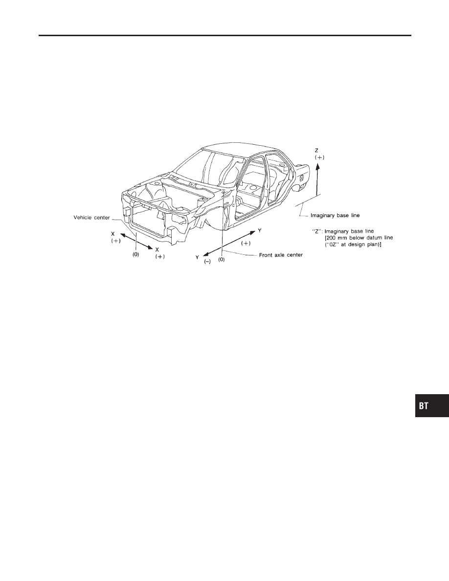
Alignment
NCBT0021
I
All dimensions indicated in figures are actual ones.
I
When using a tracking gauge, adjust both pointers to equal length. Then check the pointers and gauge
itself to make sure there is no free play.
I
When a measuring tape is used, check to be sure there is no elongation, twisting or bending.
I
Measurements should be taken at the center of the mounting holes.
I
An asterisk (*) following the value at the measuring point indicates that the measuring point on the other
side is symmetrically the same value.
I
The coordinates of the measurement points are the distances measured from the standard line of “X”, “Y”
and “Z”.
SBF874GB
GI
MA
EM
LC
EC
FE
CL
MT
AT
AX
SU
BR
ST
RS
HA
SC
EL
IDX
BODY (ALIGNMENT)
Alignment
BT-57
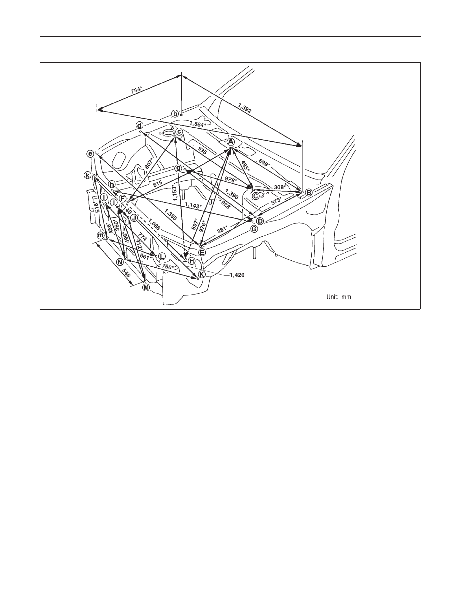
ENGINE COMPARTMENT
NCBT0021S01
Measurement
NCBT0021S0101
SBT419
BODY (ALIGNMENT)
Alignment (Cont’d)
BT-58
Нет комментариевНе стесняйтесь поделиться с нами вашим ценным мнением.
Текст