Infiniti G20 (P11). Manual — part 409
NCGI0004
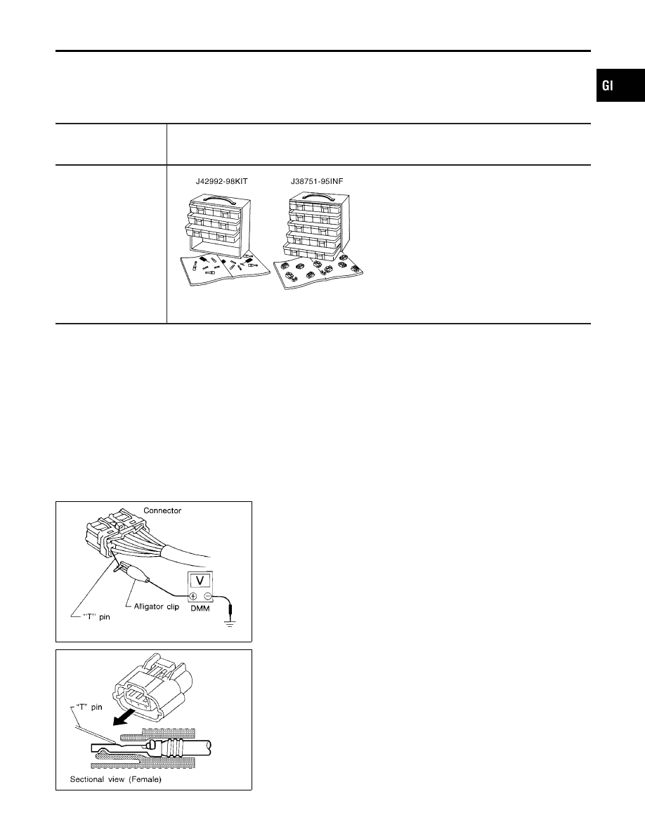
Connector and Terminal Pin Kit
NCGI0004S01
Use the connector and terminal pin kit listed below when replacing
connectors or terminals.
The connector and terminal pin kit contains some of the most
commonly used INFINITI connectors and terminals.
Tool number
(Kent-Moore No.)
Tool name
Description
—
(J38751-95INF)
Connector and terminal
pin kit
—
(J42992-98KIT)
OBD Terminal Repair Kit
SGI109A
How to Probe Connectors
NCGI0004S02
Connector damage and an intermittent connection can result from
improperly probing of the connector during circuit checks.
The probe of a digital multimeter (DMM) may not correctly fit the
connector cavity. To correctly probe the connector, follow the pro-
cedures below using a “T” pin. For the best contact grasp the “T”
pin using an alligator clip.
SGI841
PROBING FROM HARNESS SIDE
NCGI0004S0201
Standard type (not waterproof type) connector should be probed
from harness side with “T” pin.
I
If the connector has a rear cover such as a ECM
connector, remove the rear cover before probing the ter-
minal.
I
Do not probe waterproof connector from harness side.
Damage to the seal between wire and connector may
result.
SEL265V
PROBING FROM TERMINAL SIDE
NCGI0004S0202
Female terminal
I
There is a small notch above each female terminal. Probe
each terminal with the “T” pin through the notch.
Do not insert any object other than the same type male
terminal into female terminal.
MA
EM
LC
EC
FE
CL
MT
AT
AX
SU
BR
ST
RS
BT
HA
SC
EL
IDX
HOW TO CHECK TERMINAL
Connector and Terminal Pin Kit
GI-21
SEL266V
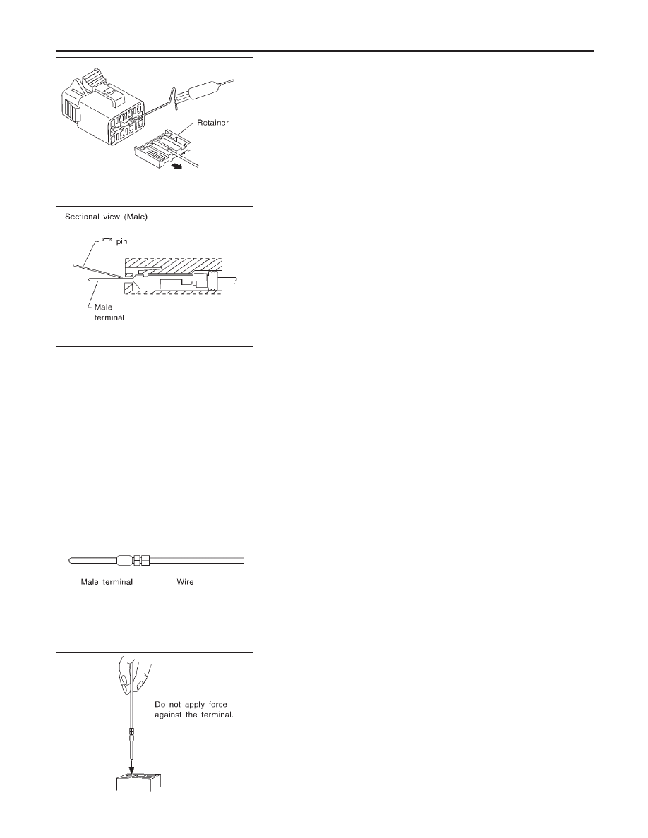
I
Some connectors do not have a notch above each terminal. To
probe each terminal, remove the connector retainer to make
contact space for probing.
SEL267V
Male terminal
Carefully probe the contact surface of each terminal using a “T” pin.
Do not bend terminal.
How to Check Enlarged Contact Spring of
Terminal
NCGI0004S03
An enlarged contact spring of a terminal may create intermittent
signals in the circuit.
If the intermittent open circuit occurs, follow the procedure below
to inspect for open wires and enlarged contact spring of female
terminal.
SEL270V
1.
Assemble a male terminal and approx. 10 cm (3.9 in) of wire.
Use a male terminal which matches the female terminal.
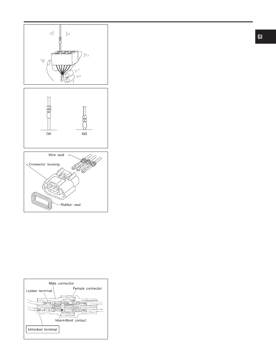
2.
Disconnect the suspected faulty connector and hold it terminal
side up.
SEL271V
3.
While holding the wire of the male terminal, try to insert the
male terminal into the female terminal.
Do not force the male terminal into the female terminal
with your hands.
HOW TO CHECK TERMINAL
How to Probe Connectors (Cont’d)
GI-22
SEL272V
4.
While moving the connector, check whether the male terminal
can be easily inserted or not.
SEL273V
I
If the male terminal can be easily inserted into the female
terminal, replace the female terminal.
SEL275V
Waterproof Connector Inspection
NCGI0004S04
If water enters the connector, it can short interior circuits. This may
lead to intermittent problems.
Check the following items to maintain the original waterproof char-
acteristics.
RUBBER SEAL INSPECTION
NCGI0004S0401
I
Most waterproof connectors are provided with a rubber seal
between the male and female connectors. If the seal is
missing, the waterproof performance may not meet specifica-
tions.
I
The rubber seal may come off when connectors are discon-
nected. Whenever connectors are reconnected, make sure the
rubber seal is properly installed on either side of male or
female connector.
WIRE SEAL INSPECTION
NCGI0004S0402
The wire seal must be installed on the wire insertion area of a
waterproof connector. Be sure that the seal is installed properly.
SEL330V
Terminal Lock Inspection
NCGI0004S05
Check for unlocked terminals by pulling wire at the end of connec-
tor. An unlocked terminal may create intermittent signals in the
circuit.
MA
EM
LC
EC
FE
CL
MT
AT
AX
SU
BR
ST
RS
BT
HA
SC
EL
IDX
HOW TO CHECK TERMINAL
How to Check Enlarged Contact Spring of Terminal (Cont’d)
GI-23
NCGI0005
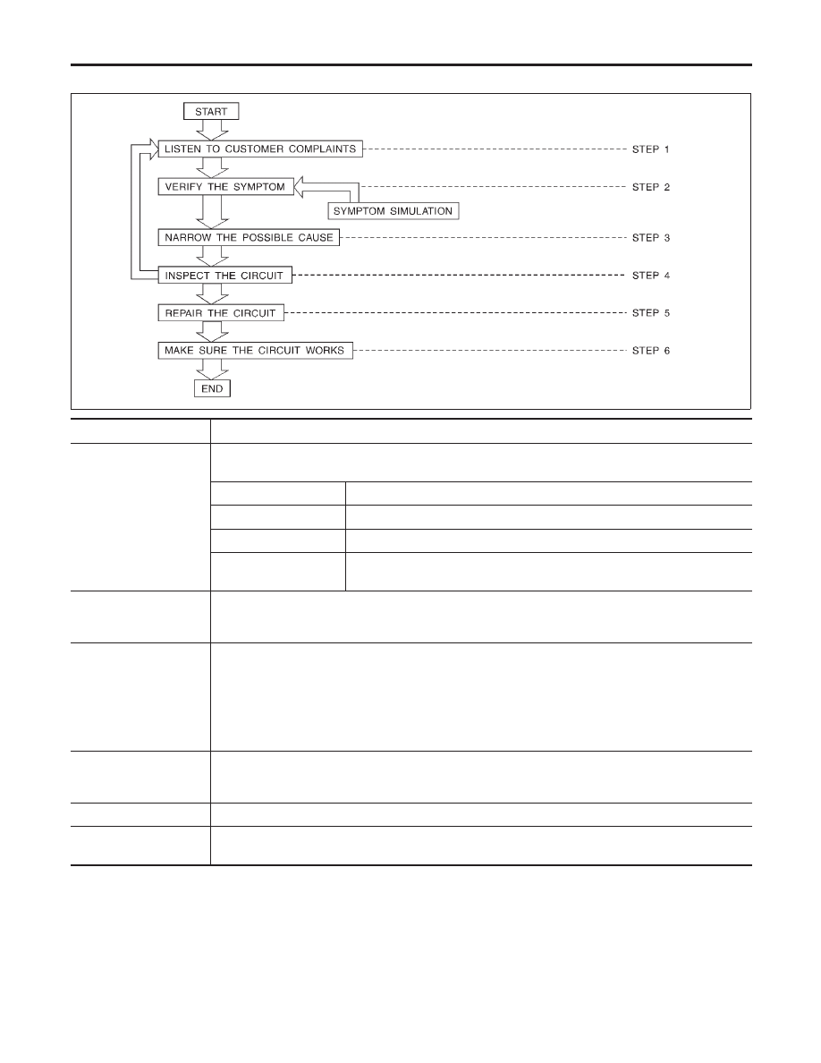
Work Flow
NCGI0005S01
SGI838
STEP
DESCRIPTION
STEP 1
Get detailed information about the conditions and the environment when the incident occurred.
The following are key pieces of information required to make a good analysis:
WHAT
Vehicle Model, Engine, Transmission and the System (i.e. Radio).
WHEN
Date, Time of Day, Weather Conditions, Frequency.
WHERE
Road Conditions, Altitude and Traffic Situation.
HOW
System Symptoms, Operating Conditions (Other Components Interaction).
Service History and if any After Market Accessories have been installed.
STEP 2
Operate the system, road test if necessary.
Verify the parameter of the incident.
If the problem can not be duplicated, refer to “Incident Simulation Tests” next page.
STEP 3
Get the proper diagnosis materials together including:
POWER SUPPLY ROUTING
System Operation Descriptions
Applicable Service Manual Sections
Check for any Service Bulletin.
Identify where to begin diagnosis based upon your knowledge of the system operation and the cus-
tomer comments.
STEP 4
Inspect the system for mechanical binding, loose connectors or wiring damage.
Determine which circuits and components are involved and diagnose using the Power Supply Routing
and Harness Layouts.
STEP 5
Repair or replace the incident circuit or component.
STEP 6
Operate the system in all modes. Verify the system works properly under all conditions. Make sure you
have not inadvertently created a new incident during your diagnosis or repair steps.
HOW TO PERFORM EFFICIENT DIAGNOSIS FOR AN ELECTRICAL INCIDENT
Work Flow
GI-24
Нет комментариевНе стесняйтесь поделиться с нами вашим ценным мнением.
Текст