Infiniti G20 (P11). Manual — part 270
SEF956N
SEF847X
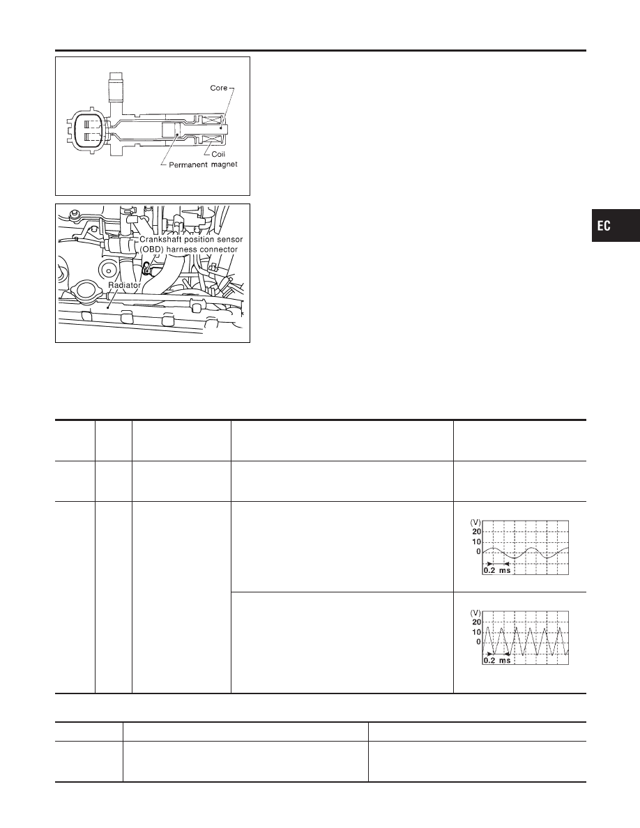
Component Description
NCEC0327
The crankshaft position sensor (OBD) is located on the transmis-
sion housing facing the gear teeth (cogs) of the flywheel or drive
plate. It detects the fluctuation of the engine revolution.
The sensor consists of a permanent magnet, core and coil.
When the engine is running, the high and low parts of the teeth
cause the gap with the sensor to change.
The changing gap causes the magnetic field near the sensor to
change.
Due to the changing magnetic field, the voltage from the sensor
changes.
The ECM receives the voltage signal and detects the fluctuation of
the engine revolution.
This sensor is not used to control the engine system.
It is used only for the on board diagnosis.
ECM Terminals and Reference Value
NCEC0328
Specification data are reference values and are measured between each terminal and ground.
CAUTION:
Do not use ECM ground terminals when measuring input/output voltage. Doing so may result in dam-
age to the ECM’s transistor. Use a ground other than ECM terminals, such as the ground.
TERMI-
NAL
NO.
WIRE
COLOR
ITEM
CONDITION
DATA (AC Voltage)
58
B
Sensors’ ground
[Engine is running]
I
Warm-up condition
I
Idle speed
Approximately 0V
65
W
Crankshaft position
sensor (OBD)
[Engine is running]
I
Warm-up condition
I
Idle speed
3 - 5V (AC range)
SEF721W
[Engine is running]
I
Engine speed is 2,000 rpm
6 - 9V (AC range)
SEF722W
On Board Diagnosis Logic
NCEC0329
DTC No.
Malfunction is detected when ...
Check Items (Possible Cause)
P1336
I
A chipping of the flywheel or drive plate gear tooth (cog)
is detected by the ECM.
I
Harness or connectors
I
Crankshaft position sensor (OBD)
I
Drive plate/Flywheel
GI
MA
EM
LC
FE
CL
MT
AT
AX
SU
BR
ST
RS
BT
HA
SC
EL
IDX
DTC P1336 CRANKSHAFT POSITION SENSOR (CKPS) (OBD) (COG)
Component Description
EC-491
SEF058Y
DTC Confirmation Procedure
NCEC0330
NOTE:
If “DTC Confirmation Procedure” has been previously conducted,
always turn ignition switch “OFF” and wait at least 10 seconds
before conducting the next test.
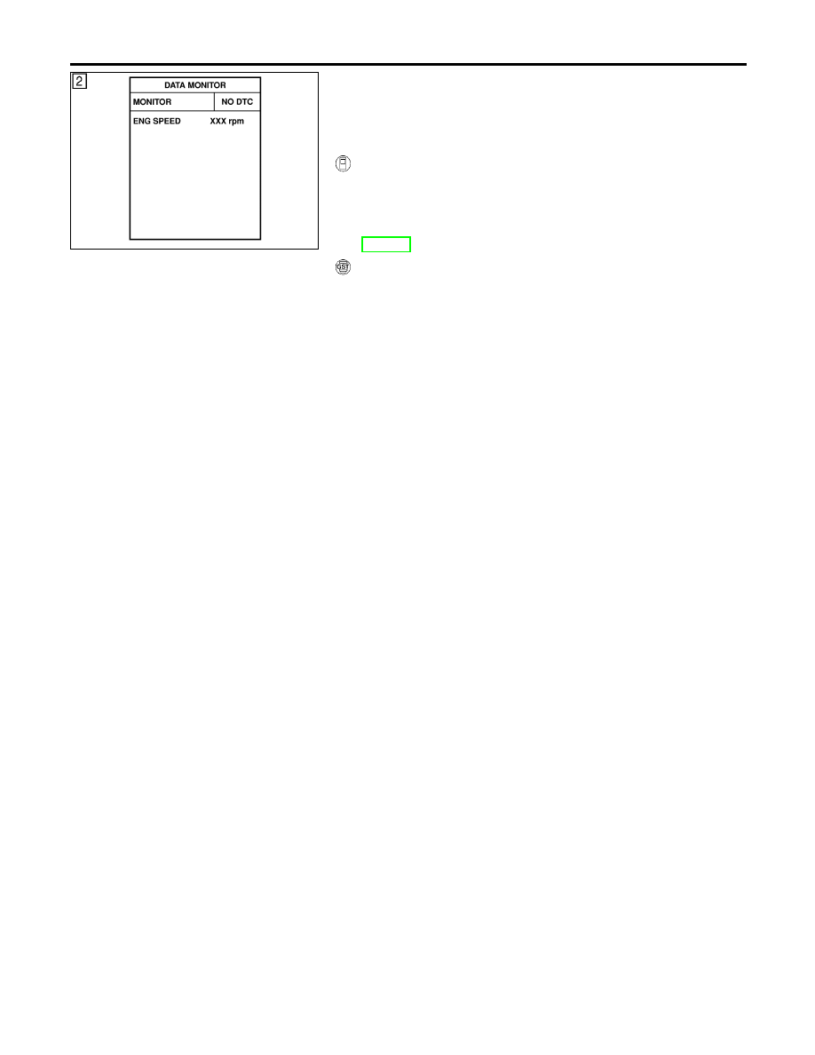
With CONSULT-II
1)
Turn ignition switch “ON” and select “DATA MONITOR” mode
with CONSULT-II.
2)
Start engine and run it for at least 4 minutes at idle speed.
3)
If 1st trip DTC is detected, go to “Diagnostic Procedure”,
EC-494.
With GST
Follow the procedure “With CONSULT-II” above.
DTC P1336 CRANKSHAFT POSITION SENSOR (CKPS) (OBD) (COG)
DTC Confirmation Procedure
EC-492
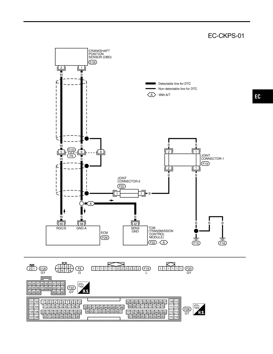
Wiring Diagram
NCEC0331
TEC709
GI
MA
EM
LC
FE
CL
MT
AT
AX
SU
BR
ST
RS
BT
HA
SC
EL
IDX
DTC P1336 CRANKSHAFT POSITION SENSOR (CKPS) (OBD) (COG)
Wiring Diagram
EC-493
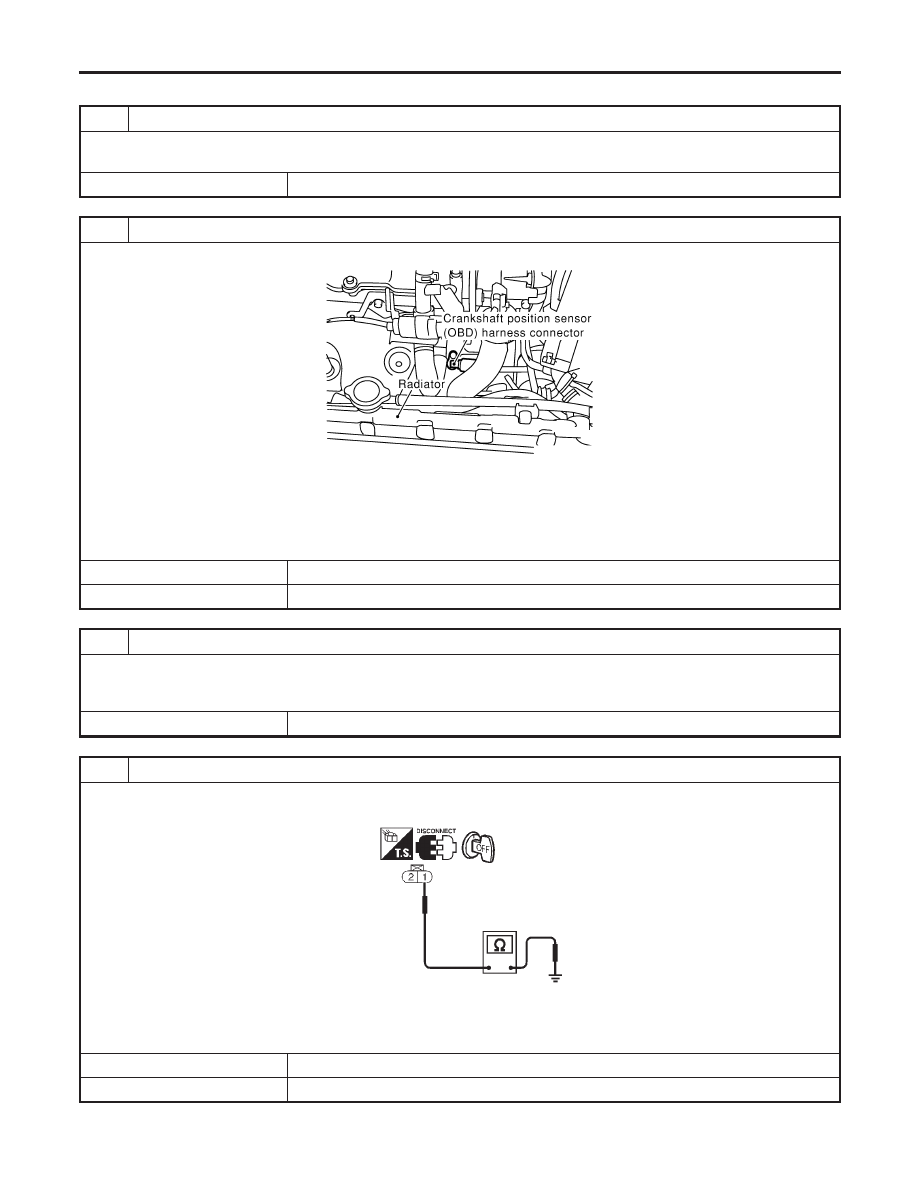
Diagnostic Procedure
NCEC0332
1
RETIGHTEN GROUND SCREWS
1. Turn ignition switch “OFF”.
2. Loosen and retighten engine ground screws.
©
GO TO 2.
2
CHECK INPUT SIGNAL CIRCUIT
1. Disconnect crankshaft position sensor (OBD) and ECM harness connectors.
SEF847X
2. Check continuity between ECM terminal 65 and terminal 2.
Refer to Wiring Diagram.
Continuity should exist.
3. Also check harness for short to ground and short to power.
OK or NG
OK
©
GO TO 4.
NG
©
GO TO 3.
3
DETECT MALFUNCTIONING PART
Check the following.
I
Harness connectors F6, E123
I
Harness for open or short between crankshaft position sensor (OBD) and ECM
©
Repair open circuit or short to ground or short to power in harness or connectors.
4
CHECK GROUND CIRCUIT
1. Reconnect ECM harness connectors.
2. Check harness continuity between CKPS (OBD) terminal 1 and engine ground.
SEF229W
Continuity should exist.
3. Also check harness for short to power.
OK or NG
OK
©
GO TO 6.
NG
©
GO TO 5.
DTC P1336 CRANKSHAFT POSITION SENSOR (CKPS) (OBD) (COG)
Diagnostic Procedure
EC-494
Нет комментариевНе стесняйтесь поделиться с нами вашим ценным мнением.
Текст