Infiniti G20 (P11). Manual — part 184
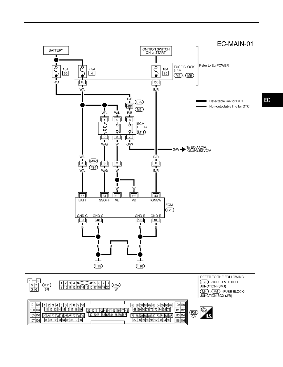
Main Power Supply and Ground Circuit
WIRING DIAGRAM
NCEC0047
TEC696
GI
MA
EM
LC
FE
CL
MT
AT
AX
SU
BR
ST
RS
BT
HA
SC
EL
IDX
TROUBLE DIAGNOSIS FOR POWER SUPPLY
Main Power Supply and Ground Circuit
EC-147

ECM TERMINALS AND REFERENCE VALUE
NCEC0048
Specification data are reference values and are measured between each terminal and ground.
CAUTION:
Do not use ECM ground terminals when measuring input/output voltage. Doing so may result in dam-
age to the ECM’s transistor. Use a ground other than ECM terminals, such as the ground.
TERMI-
NAL
NO.
WIRE
COLOR
ITEM
CONDITION
DATA (DC Voltage)
31
W/G
ECM relay (Self shut-off)
[Engine is running]
[Ignition switch “OFF”]
I
For 5 seconds after turning ignition switch “OFF”
0 - 1V
[Ignition switch “OFF”]
I
5 seconds passed after turning ignition switch
“OFF”
BATTERY VOLTAGE
(11 - 14V)
43
B/R
Ignition switch
[Ignition switch “OFF”]
0V
[Ignition switch “ON”]
BATTERY VOLTAGE
(11 - 14V)
48
B
ECM ground
[Engine is running]
I
Idle speed
Engine ground
57
B
ECM ground
[Engine is running]
I
Idle speed
Engine ground
67
W/L
Power supply for ECM
(Back-up)
[Ignition switch “OFF”]
BATTERY VOLTAGE
(11 - 14V)
106
B
ECM ground
[Engine is running]
I
Idle speed
Engine ground
108
B
ECM ground
[Engine is running]
I
Idle speed
Engine ground
110
112
W
W
Power supply for ECM
[Ignition switch “ON”]
BATTERY VOLTAGE
(11 - 14V)
DIAGNOSTIC PROCEDURE
NCEC0049
1
INSPECTION START
Start engine.
Is engine running?
Yes or No
Yes
©
GO TO 8.
No
©
GO TO 2.
TROUBLE DIAGNOSIS FOR POWER SUPPLY
Main Power Supply and Ground Circuit (Cont’d)
EC-148
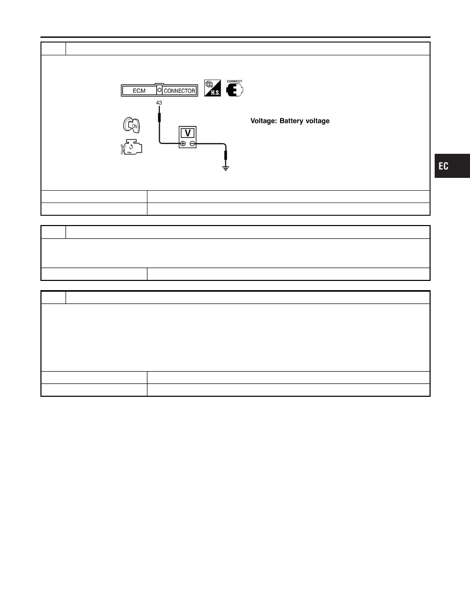
2
CHECK ECM POWER SUPPLY CIRCUIT-I
1. Turn ignition switch “OFF” and then “ON”.
2. Check voltage between ECM terminal 43 and ground with CONSULT-II or tester.
SEF291X
OK or NG
OK
©
GO TO 4.
NG
©
GO TO 3.
3
DETECT MALFUNCTIONING PART
Check the following.
I
Harness connectors M62, F24
I
Harness for open or short between ECM and 10A fuse
©
Repair harness or connectors.
4
CHECK ECM GROUND CIRCUIT FOR OPEN AND SHORT-I
1. Turn ignition switch “OFF”.
2. Disconnect ECM harness connector.
3. Check harness continuity between ECM terminals 48, 57, 106, 108 and engine ground.
Refer to WIRING DIAGRAM.
Continuity should exist.
4. Also check harness for short to power.
OK or NG
OK
©
GO TO 5.
NG
©
Repair open circuit or short to power in harness or connectors.
GI
MA
EM
LC
FE
CL
MT
AT
AX
SU
BR
ST
RS
BT
HA
SC
EL
IDX
TROUBLE DIAGNOSIS FOR POWER SUPPLY
Main Power Supply and Ground Circuit (Cont’d)
EC-149
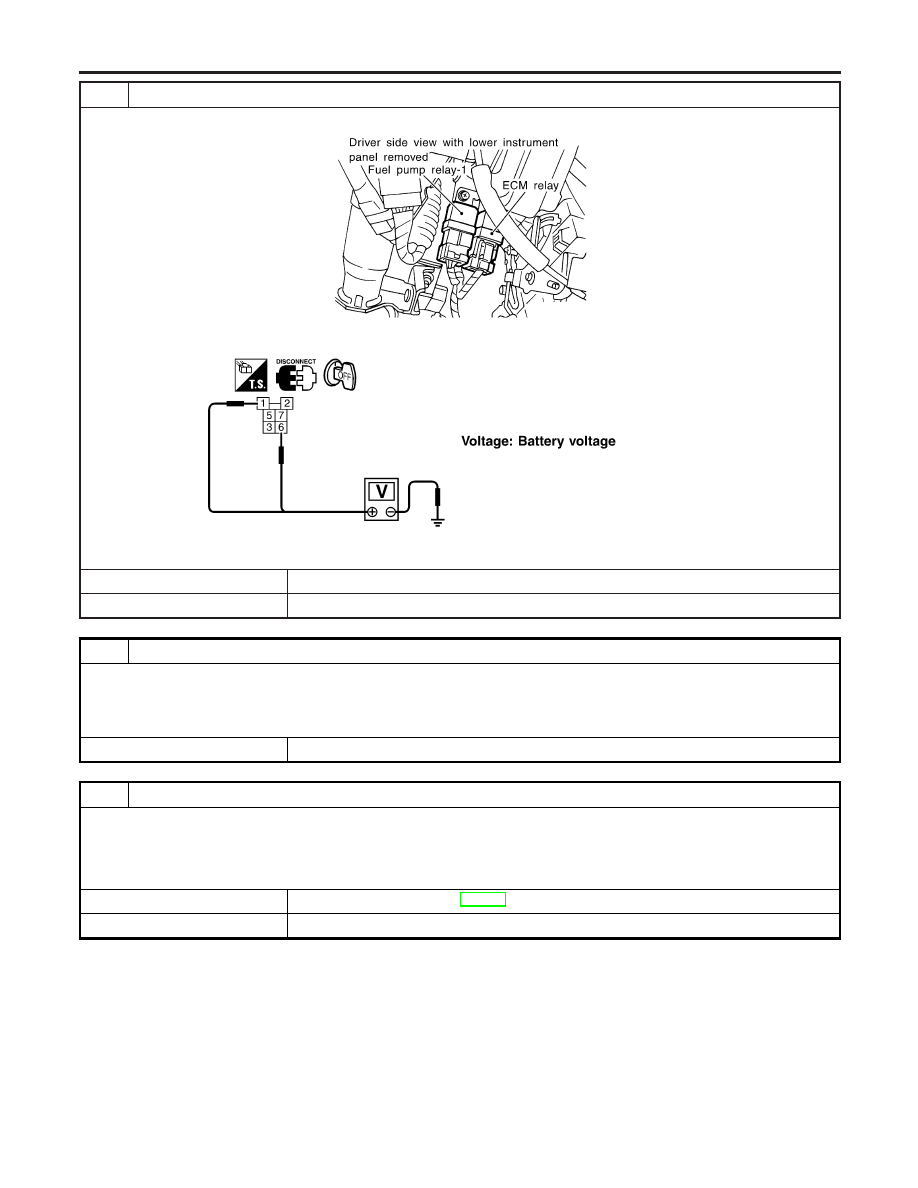
5
CHECK ECM POWER SUPPLY CIRCUIT-II
1. Disconnect ECM relay.
SEF185XA
2. Check voltage between ECM relay terminals 1, 6 and ground with CONSULT-II or tester.
SEF101Y
OK or NG
OK
©
GO TO 7.
NG
©
GO TO 6.
6
DETECT MALFUNCTIONING PART
Check the following.
I
15A fuse and 7.5A fuse
I
Harness connectors E75, M6
I
Harness for open or short between ECM relay and battery
©
Repair open circuit or short to ground or short to power in harness or connectors.
7
CHECK OUTPUT SIGNAL CIRCUIT FOR OPEN AND SHORT
1. Check harness continuity between ECM terminal 31 and ECM relay terminal 2.
Continuity should exist.
2. Also check harness for short to ground and short to power.
OK or NG
OK
©
Go to “IGNITION SIGNAL”, EC-590.
NG
©
Repair open circuit or short to ground or short to power in harness or connectors.
TROUBLE DIAGNOSIS FOR POWER SUPPLY
Main Power Supply and Ground Circuit (Cont’d)
EC-150
Нет комментариевНе стесняйтесь поделиться с нами вашим ценным мнением.
Текст