Infiniti G20 (P11). Manual — part 109
SBR822BA
SBR823BA
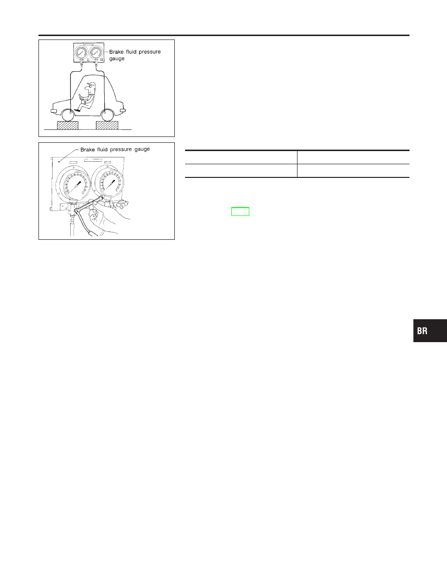
Inspection
NCBR0014
CAUTION:
I
Carefully monitor brake fluid level at master cylinder.
I
Use new brake fluid “DOT 3”.
I
Be careful not to splash brake fluid on painted areas; it
may cause paint damage. If brake fluid is splashed on
paint areas, wash it away with water immediately.
1.
Connect Tool to air bleeders of front and rear brakes on either
LH and RH side.
2.
Bleed air from the Tool.
3.
Check fluid pressure by depressing brake pedal.
Unit: kPa (kg/cm
2
, psi)
Applied pressure (Front brake)
7,355 (75, 1,067)
Output pressure (Rear brake)
5,100 - 5,492 (52 - 56, 739 - 796)
If output pressure is out of specification, replace dual propor-
tioning valve.
4.
Bleed air after disconnecting the Tool. Refer to “Bleeding Brake
System”, BR-8.
GI
MA
EM
LC
EC
FE
CL
MT
AT
AX
SU
ST
RS
BT
HA
SC
EL
IDX
DUAL PROPORTIONING VALVE
Inspection
BR-11
Removal and Installation
NCBR0015
SBR109E
SBR997
Inspection
NCBR0016
Check brake pedal for following items.
I
Brake pedal bend
I
Clevis pin deformation
I
Crack of any welded portion
I
Crack or deformation of clevis pin stopper
SBR323E
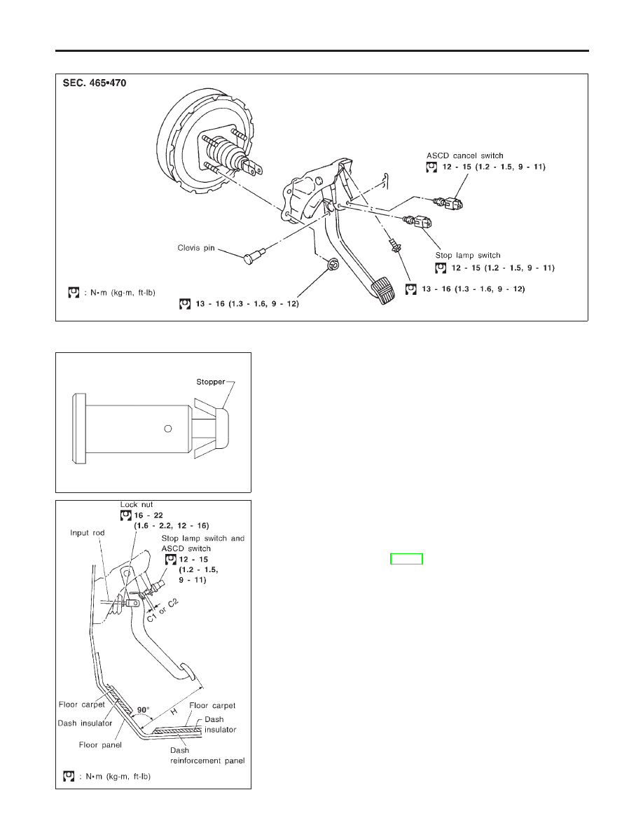
Adjustment
NCBR0017
Check brake pedal free height from metal panel. Adjust if neces-
sary.
H: Free height
Refer to SDS, BR-79.
C
1
, C
2
: Clearance between pedal stopper and threaded
end of stop lamp switch and ASCD switch
0.3 - 1.0 mm (0.012 - 0.039 in)
BRAKE PEDAL AND BRACKET
Removal and Installation
BR-12
SBR229E
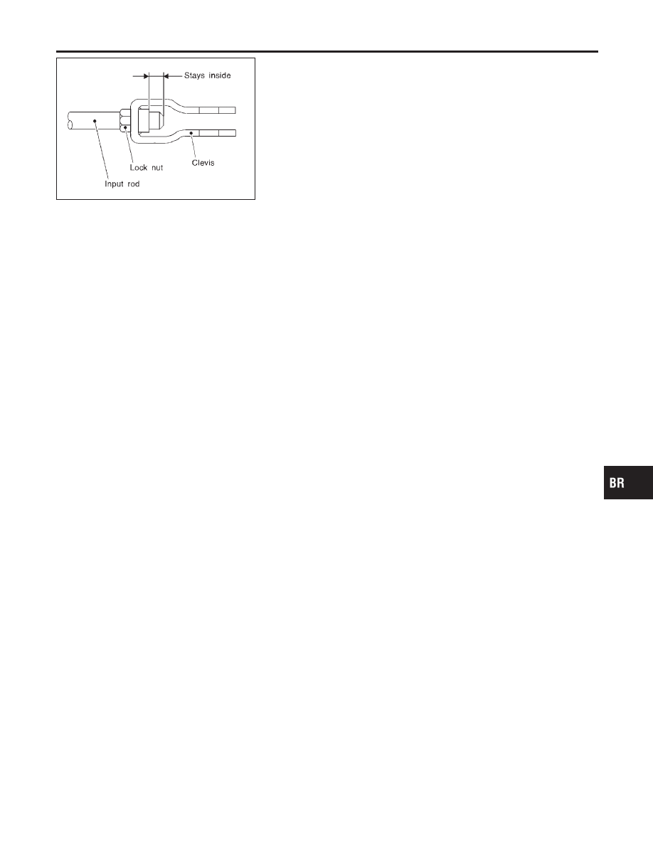
1.
Loosen lock nut and adjust pedal free height by turning brake
booster input rod. Then tighten lock nut.
2.
Check pedal free play.
Make sure that stop lamps go off when pedal is released.
3.
Check brake pedal’s depressed height while engine is running.
If lower than specification, check brake system for leaks, accu-
mulation of air or any damage to components (master cylinder,
wheel cylinder, etc.); then make necessary repairs.
GI
MA
EM
LC
EC
FE
CL
MT
AT
AX
SU
ST
RS
BT
HA
SC
EL
IDX
BRAKE PEDAL AND BRACKET
Adjustment (Cont’d)
BR-13
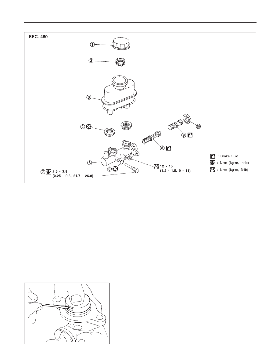
Removal
NCBR0018
SBR324E
1.
Reservor cap
2.
Oil filter
3.
Reservor tank
4.
Seal
5.
Cylinder body
6.
O-ring
7.
Piston stopper
8.
Secondary piston assembly
9.
Primary piston assembly
10. Stopper cap
CAUTION:
Be careful not to splash brake fluid on painted areas; it may
cause paint damage. If brake fluid is splashed on painted
areas, wash it away with water immediately.
1.
Connect a vinyl tube to air bleeder valve.
2.
Drain brake fluid from each air bleeder valve, depressing brake
pedal to empty fluid from master cylinder.
3.
Remove brake pipe flare nuts.
4.
Remove master cylinder mounting nuts.
SBR938A
Disassembly
NCBR0019
1.
Bend claws of stopper cap outward.
MASTER CYLINDER
Removal
BR-14
Нет комментариевНе стесняйтесь поделиться с нами вашим ценным мнением.
Текст