Infiniti G20 (P11). Manual — part 197
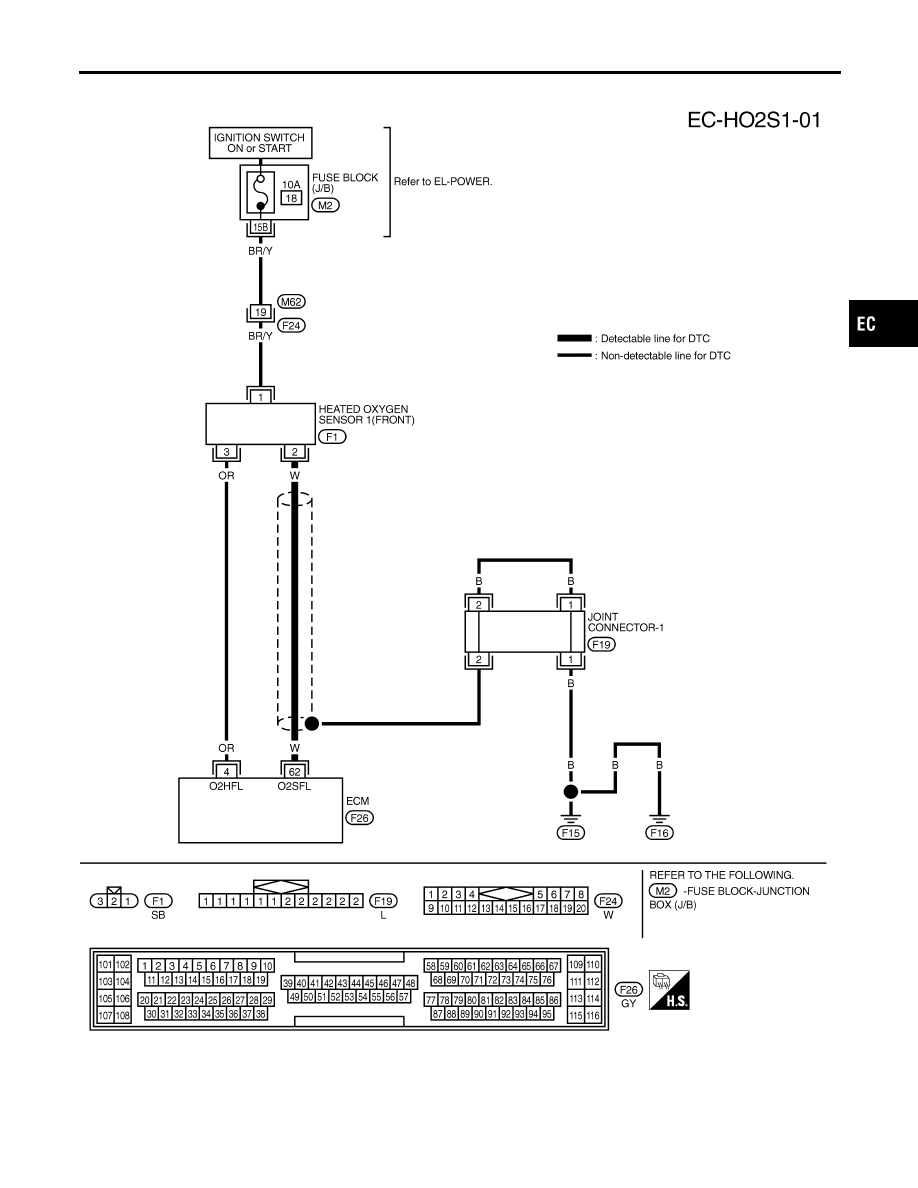
Wiring Diagram
NCEC0100
TEC837
GI
MA
EM
LC
FE
CL
MT
AT
AX
SU
BR
ST
RS
BT
HA
SC
EL
IDX
DTC P0130 HEATED OXYGEN SENSOR 1 (FRONT) (CIRCUIT)
Wiring Diagram
EC-199
Diagnostic Procedure
NCEC0101
1
INSPECTION START
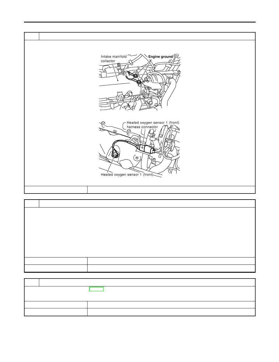
1. Turn ignition switch “OFF”.
2. Loosen and retighten engine ground screws.
SEF839X
3. Disconnect heated oxygen sensor 1 (front) harness connector.
SEF917Z
©
GO TO 2.
2
CHECK INPUT SIGNAL CIRCUIT
1. Disconnect ECM harness connector.
2. Check harness continuity between ECM terminal 62 and HO2S1 terminal 2.
Refer to Wiring Diagram.
Continuity should exist.
3. Check harness continuity between ECM terminal 62 (or HO2S1 terminal 2) and ground.
Refer to Wiring Diagram.
Continuity should not exist.
4. Also check harness for short to power.
OK or NG
OK
©
GO TO 3.
NG
©
Repair open circuit or short to ground or short to power in harness or connectors.
3
CHECK HEATED OXYGEN SENSOR 1 (FRONT)
Refer to “Component Inspection”, EC-202.
OK or NG
OK
©
GO TO 4.
NG
©
Replace heated oxygen sensor 1 (front).
DTC P0130 HEATED OXYGEN SENSOR 1 (FRONT) (CIRCUIT)
Diagnostic Procedure
EC-200
4
CHECK SHIELD CIRCUIT
1. Turn ignition switch “OFF”.
2. Disconnect joint connector-1.
3. Check the following.
I
Continuity between joint connector-1 terminal 2 and ground
I
Joint connector-1
(Refer to EL-274, “HARNESS LAYOUT”.)
Continuity should exist.
4. Also check harness for short to power.
5. Then reconnect joint connector.
OK or NG
OK
©
GO TO 5.
NG
©
Repair open circuit or short to power in harness or connectors.
5
CHECK INTERMITTENT INCIDENT
Perform “TROUBLE DIAGNOSIS FOR INTERMITTENT INCIDENT”, EC-146.
©
INSPECTION END
GI
MA
EM
LC
FE
CL
MT
AT
AX
SU
BR
ST
RS
BT
HA
SC
EL
IDX
DTC P0130 HEATED OXYGEN SENSOR 1 (FRONT) (CIRCUIT)
Diagnostic Procedure (Cont’d)
EC-201
SEF646Y
SEF217YA
Component Inspection
=NCEC0102
HEATED OXYGEN SENSOR 1 (FRONT)
NCEC0102S01
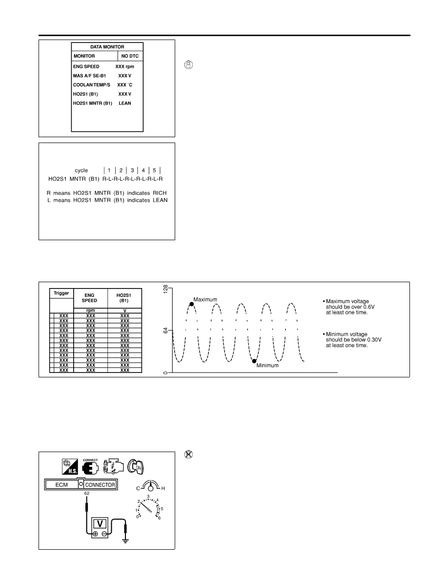
With CONSULT-II
1)
Start engine and warm it up to normal operating temperature.
2)
Select “MANU TRIG” in “DATA MONITOR” mode, and select
“HO2S1 (B1)” and “HO2S1 MNTR (B1)”.
3)
Hold engine speed at 2,000 rpm under no load during the fol-
lowing steps.
4)
Touch “RECORD” on CONSULT-II screen.
5)
Check the following.
I
“HO2S1 MNTR (B1)” in “DATA MONITOR” mode changes from
“RICH” to “LEAN” to “RICH” 5 times in 10 seconds.
5 times (cycles) are counted as shown below:
R = “HO2S1 MNTR (B1)”, “RICH”
L = “HO2S1 MNTR (B1)”, “LEAN”
I
“HO2S1 (B1)” voltage goes above 0.6V at least once.
I
“HO2S1 (B1)” voltage goes below 0.3V at least once.
I
“HO2S1 (B1)” voltage never exceeds 1.0V.
CAUTION:
I
Discard any heated oxygen sensor which has been
dropped from a height of more than 0.5 m (19.7 in) onto a
hard surface such as a concrete floor; use a new one.
I
Before installing new oxygen sensor, clean exhaust sys-
tem threads using Oxygen Sensor Thread Cleaner tool
J-43897-18 or J-43897-12 and approved anti-seize lubri-
cant.
SEF648Y
SEF011X
Without CONSULT-II
1)
Start engine and warm it up to normal operating temperature.
2)
Set voltmeter probes between ECM terminal 62 [Heated oxy-
gen sensor 1 (front) signal] and engine ground.
3)
Check the following with engine speed held at 2,000 rpm con-
stant under no load.
I
The voltage fluctuates between 0 to 0.3V and 0.6 to 1.0V more
than five times within 10 seconds.
1 time: 0 - 0.3V
→
0.6 - 1.0V
→
0 - 0.3V
2 times: 0 - 0.3V
→
0.6 - 1.0V
→
0 - 0.3V
→
0.6 - 1.0V
→
0
- 0.3V
DTC P0130 HEATED OXYGEN SENSOR 1 (FRONT) (CIRCUIT)
Component Inspection
EC-202
Нет комментариевНе стесняйтесь поделиться с нами вашим ценным мнением.
Текст