Infiniti G20 (P11). Manual — part 47
2
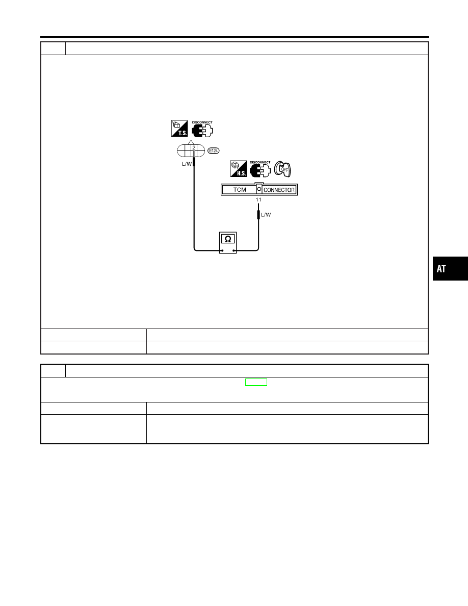
CHECK POWER SOURCE CIRCUIT
1. Turn ignition switch to “OFF” position.
2. Disconnect TCM harness connector.
3. Check continuity between terminal 2 and TCM harness connector terminal 11.
Continuity should exist.
SAT901J
If OK, check harness for short to ground and short to power.
4. Reinstall any part removed.
OK or NG
OK
©
GO TO 3.
NG
©
Repair open circuit or short to ground or short to power in harness or connectors.
3
CHECK DTC
Perform Diagnostic Trouble Code (DTC) confirmation procedure, AT-182.
OK or NG
OK
©
INSPECTION END
NG
©
1. Perform TCM input/output signal inspection.
2. If NG, recheck TCM pin terminals for damage or loose connection with harness con-
nector.
GI
MA
EM
LC
EC
FE
CL
MT
AX
SU
BR
ST
RS
BT
HA
SC
EL
IDX
DTC P0750 SHIFT SOLENOID VALVE A
Diagnostic Procedure (Cont’d)
AT-185
SAT056K
Component Inspection
NCAT0066
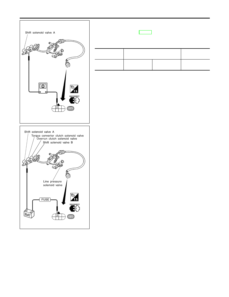
SHIFT SOLENOID VALVE A
NCAT0066S01
I
For removal, refer to AT-280.
Resistance Check
NCAT0066S0101
I
Check resistance between two terminals.
Solenoid valve
Terminal No.
Resistance
(Approx.)
Shift solenoid
valve A
2
Ground
20 - 30
Ω
SAT903JA
Operation Check
NCAT0066S0102
I
Check solenoid valve by listening for its operating sound while
applying battery voltage to the terminal and ground.
DTC P0750 SHIFT SOLENOID VALVE A
Component Inspection
AT-186
SAT283HB
Description
NCAT0067
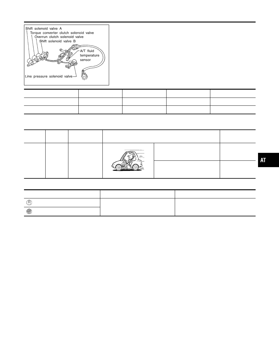
Shift solenoid valves A and B are turned “ON” or “OFF” by the TCM
in response to signals sent from the PNP switch, vehicle speed and
throttle position sensors. Gears will then be shifted to the optimum
position.
Gear position
1
2
3
4
Shift solenoid valve A
ON (Closed)
OFF (Open)
OFF (Open)
ON (Closed)
Shift solenoid valve B
ON (Closed)
ON (Closed)
OFF (Open)
OFF (Open)
TCM TERMINALS AND REFERENCE VALUE
NCAT0067S01
Remarks: Specification data are reference values.
Terminal
No.
Wire color
Item
Condition
Judgement stan-
dard
12
L/Y
Shift solenoid
valve B
When shift solenoid valve B oper-
ates.
(When driving in “D
1
” or “D
2
”.)
Battery voltage
When shift solenoid valve B does
not operate.
(When driving in “D
3
” or “D
4
”.)
1V or less
ON BOARD DIAGNOSIS LOGIC
NCAT0067S02
Diagnostic trouble code
Malfunction is detected when ...
Check items (Possible cause)
: SFT SOL B/CIRC
TCM detects an improper voltage drop
when it tries to operate the solenoid
valve.
I
Harness or connectors
(The solenoid circuit is open or shorted.)
I
Shift solenoid valve B
: P0755
GI
MA
EM
LC
EC
FE
CL
MT
AX
SU
BR
ST
RS
BT
HA
SC
EL
IDX
DTC P0755 SHIFT SOLENOID VALVE B
Description
AT-187
SAT014K
SEF949Y
DIAGNOSTIC TROUBLE CODE (DTC) CONFIRMATION
PROCEDURE
NCAT0067S03
CAUTION:
Always drive vehicle at a safe speed.
NOTE:
If “DIAGNOSTIC TROUBLE CODE CONFIRMATION PROCE-
DURE” has been previously conducted, always turn ignition
switch “OFF” and wait at least 5 seconds before conducting
the next test.
After the repair, perform the following procedure to confirm the
malfunction is eliminated.
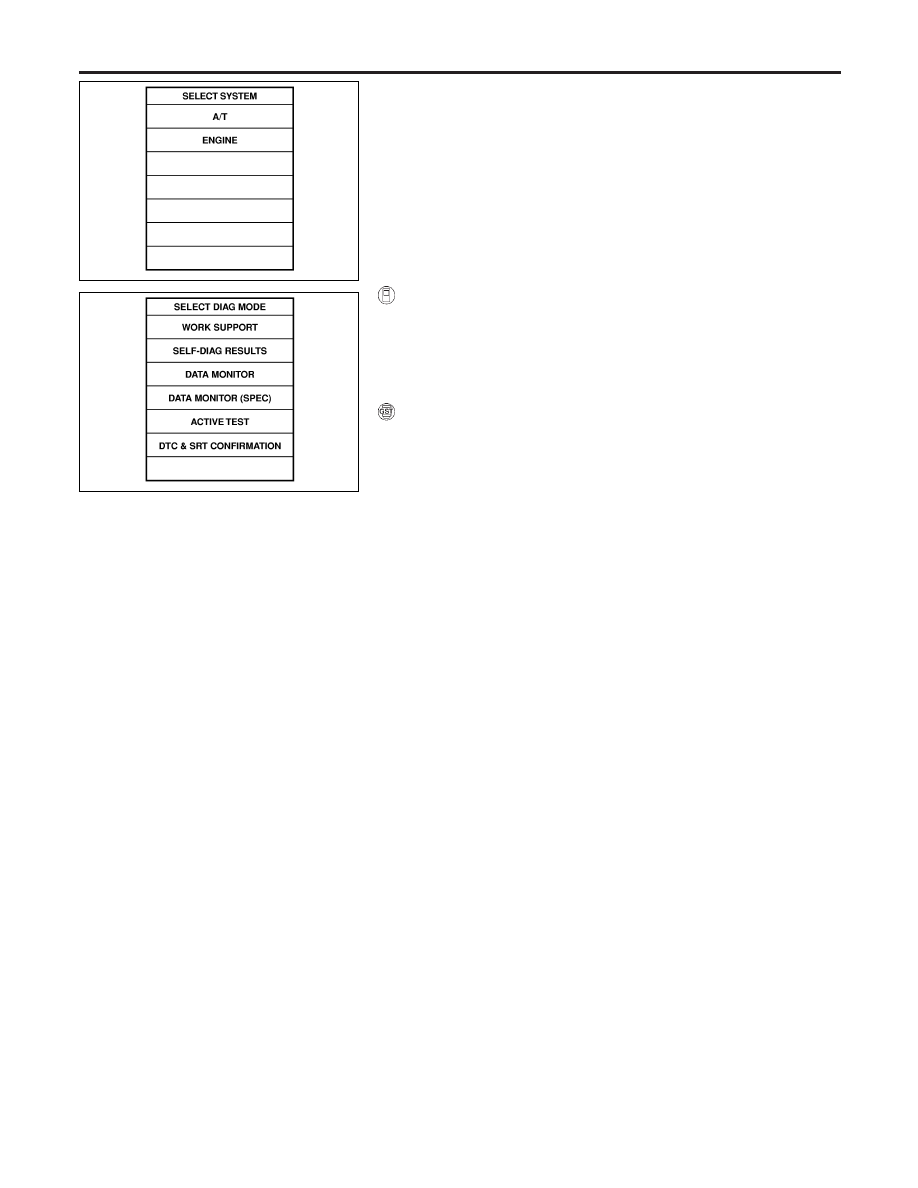
With CONSULT-II
1)
Turn ignition switch “ON” and select “DATA MONITOR” mode
for “ENGINE” with CONSULT-II.
2)
Start engine.
3)
Drive vehicle in D position and allow the transmission to shift
1
,
2
,
3 (“GEAR”).
With GST
Follow the procedure “With CONSULT-II”.
DTC P0755 SHIFT SOLENOID VALVE B
Description (Cont’d)
AT-188
Нет комментариевНе стесняйтесь поделиться с нами вашим ценным мнением.
Текст