Infiniti G20 (P11). Manual — part 217
On Board Diagnosis Logic
NCEC0192
With the Air/Fuel Mixture Ratio Self-Learning Control, the actual mixture ratio can be brought closely to the
theoretical mixture ratio based on the mixture ratio feedback signal from the heated oxygen sensor 1 (front).
The ECM calculates the necessary compensation to correct the offset between the actual and the theoretical
ratios.
In case the amount of the compensation value is extremely large (The actual mixture ratio is too rich.), the
ECM judges the condition as the fuel injection system malfunction and lights up the MIL (2 trip detection logic).
Sensor
Input Signal to ECM
ECM func-
tion
Actuator
Heated oxygen sensor 1 (front)
Density of oxygen in exhaust gas
(Mixture ratio feedback signal)
Fuel injec-
tion & mix-
ture ratio
control
Injectors
DTC No.
Malfunction is detected when ...
Check Items (Possible Cause)
P0172
I
Fuel injection system does not operate properly.
I
The amount of mixture ratio compensation is too large.
(The mixture ratio is too rich.)
I
Heated oxygen sensor 1 (front)
I
Injectors
I
Exhaust gas leaks
I
Incorrect fuel pressure
I
Mass air flow sensor
SEF215Z
SEF058Y
DTC Confirmation Procedure
NCEC0193
NOTE:
If “DTC Confirmation Procedure ” has been previously conducted,
always turn ignition switch “OFF” and wait at least 10 seconds
before conducting the next test.
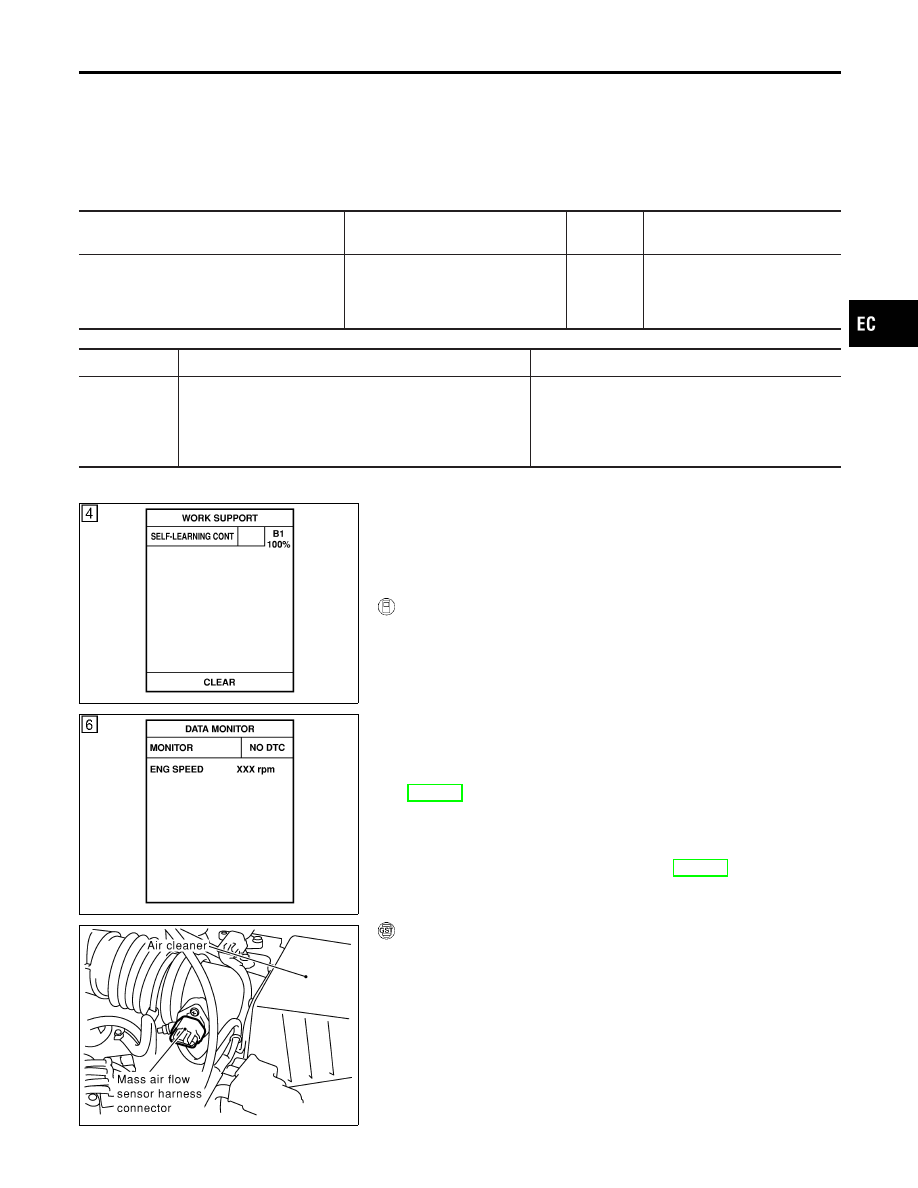
With CONSULT-II
1)
Start engine and warm it up to normal operating temperature.
2)
Turn ignition switch “OFF” and wait at least 10 seconds.
3)
Turn ignition switch “ON” and select “SELF-LEARNING CONT”
in “WORK SUPPORT” mode with CONSULT-II.
4)
Clear the self-learning control coefficient by touching “CLEAR”.
5)
Select “DATA MONITOR” mode with CONSULT-II.
6)
Start engine again and let it idle for at least 10 minutes.
The 1st trip DTC P0172 should be detected at this stage, if a
malfunction exists. If so, go to “Diagnostic Procedure”,
EC-282.
7)
If it is difficult to start engine at step 6, the fuel injection sys-
tem has a malfunction.
8)
Crank engine while depressing accelerator pedal. If engine
starts, go to “Diagnostic Procedure”, EC-282. If engine does
not start, remove ignition plugs and check for fouling, etc.
SEF840X
With GST
1)
Start engine and warm it up to normal operating temperature.
2)
Turn ignition switch “OFF” and wait at least 10 seconds.
3)
Disconnect mass air flow sensor harness connector. Then
restart and run engine for at least 3 seconds at idle speed.
4)
Stop engine and reconnect mass air flow sensor harness con-
nector.
5)
Select “MODE 7” with GST. Make sure 1st trip DTC P0100 is
detected.
6)
Select “MODE 4” with GST and erase the 1st trip DTC P0100.
GI
MA
EM
LC
FE
CL
MT
AT
AX
SU
BR
ST
RS
BT
HA
SC
EL
IDX
DTC P0172 FUEL INJECTION SYSTEM FUNCTION (RICH SIDE)
On Board Diagnosis Logic
EC-279
7)
Start engine again and run it for at least 10 minutes at idle
speed.
8)
Select “MODE 7” with GST. The 1st trip DTC P0172 should be
detected at this stage, if a malfunction exists. If so, go to
“Diagnostic Procedure”, EC-282.
9)
If it is difficult to start engine at step 8, the fuel injection sys-
tem has a malfunction.
10) Crank engine while depressing accelerator pedal.
If engine starts, go to “Diagnostic Procedure”, EC-282. If
engine does not start, remove ignition plugs and check for
fouling, etc.
DTC P0172 FUEL INJECTION SYSTEM FUNCTION (RICH SIDE)
DTC Confirmation Procedure (Cont’d)
EC-280
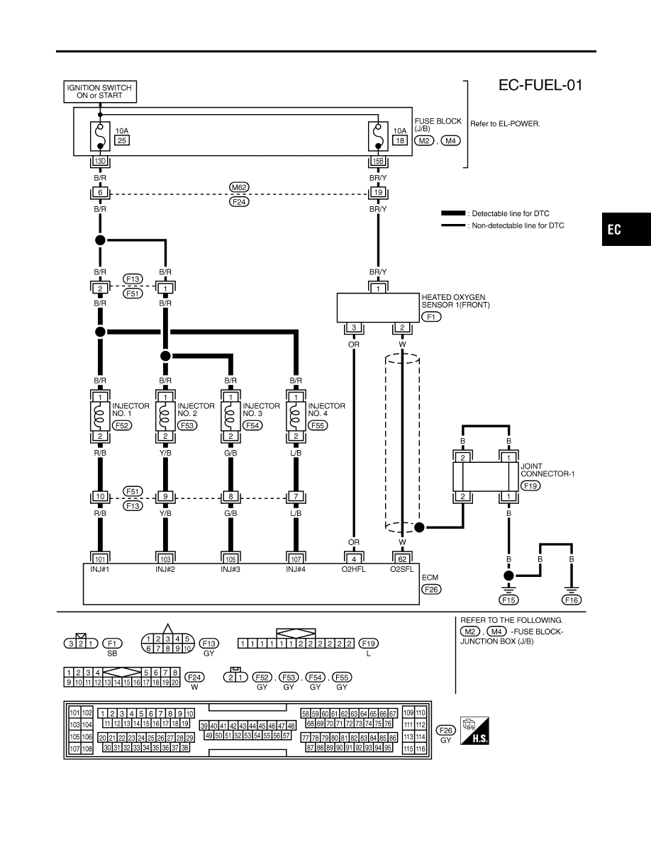
Wiring Diagram
NCEC0194
TEC841
GI
MA
EM
LC
FE
CL
MT
AT
AX
SU
BR
ST
RS
BT
HA
SC
EL
IDX
DTC P0172 FUEL INJECTION SYSTEM FUNCTION (RICH SIDE)
Wiring Diagram
EC-281
Diagnostic Procedure
NCEC0195
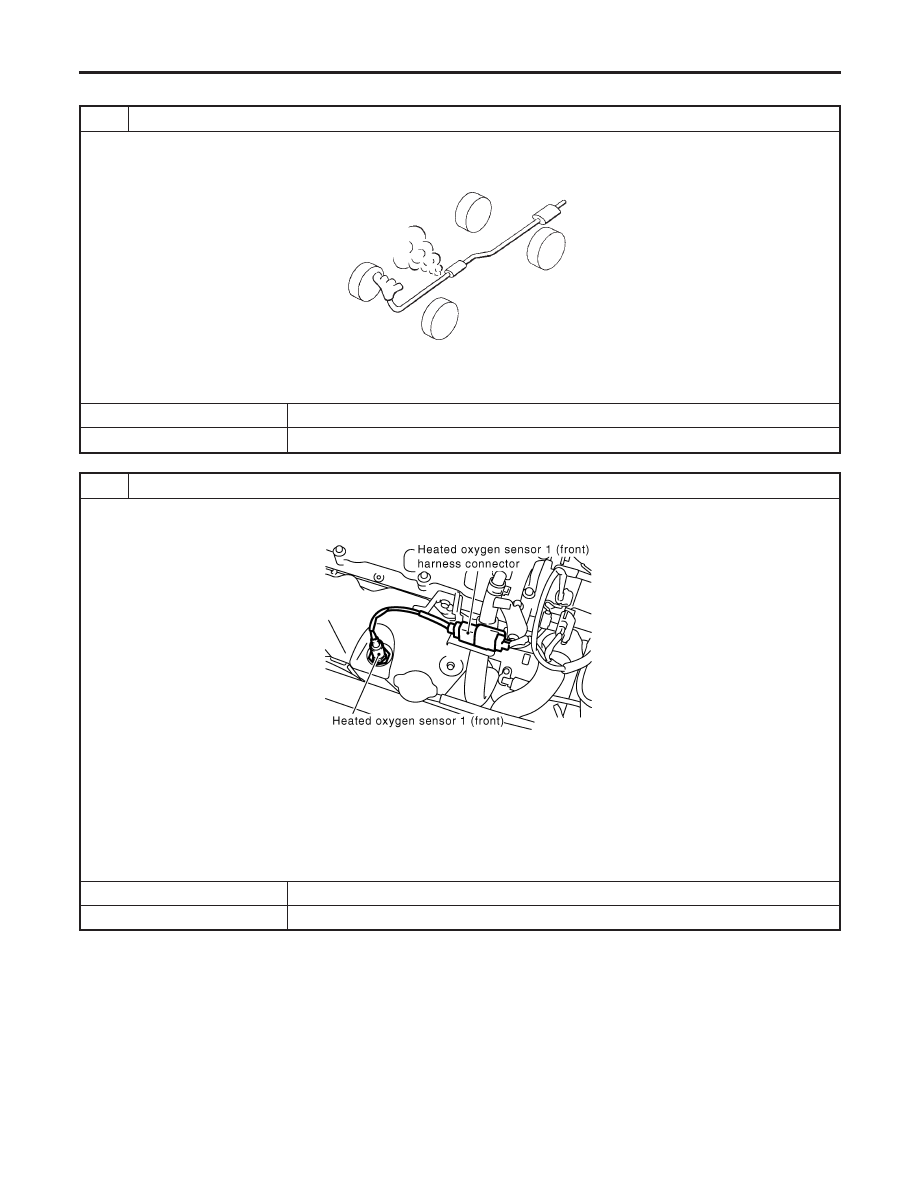
1
CHECK FOR EXHAUST AIR LEAK
1. Start engine and run it at idle.
2. Listen for an exhaust air leak before the three way catalyst.
SEF099P
OK or NG
OK
©
GO TO 2.
NG
©
Repair or replace.
2
CHECK HEATED OXYGEN SENSOR 1 (FRONT) CIRCUIT
1. Turn ignition switch “OFF”.
2. Disconnect heated oxygen sensor 1 (front) harness connector and ECM harness connector.
SEF917Z
3. Check harness continuity between ECM terminal 62 and HO2S1 terminal 2.
Refer to Wiring Diagram.
Continuity should exist.
4. Check harness continuity between ECM terminal 62 (or HO2S1 terminal 2) and ground.
Refer to Wiring Diagram.
Continuity should not exist.
5. Also check harness for short to ground and short to power.
OK or NG
OK
©
GO TO 3.
NG
©
Repair open circuit or short to ground or short to power in harness or connectors.
DTC P0172 FUEL INJECTION SYSTEM FUNCTION (RICH SIDE)
Diagnostic Procedure
EC-282
Нет комментариевНе стесняйтесь поделиться с нами вашим ценным мнением.
Текст