Infiniti G20 (P11). Manual — part 93
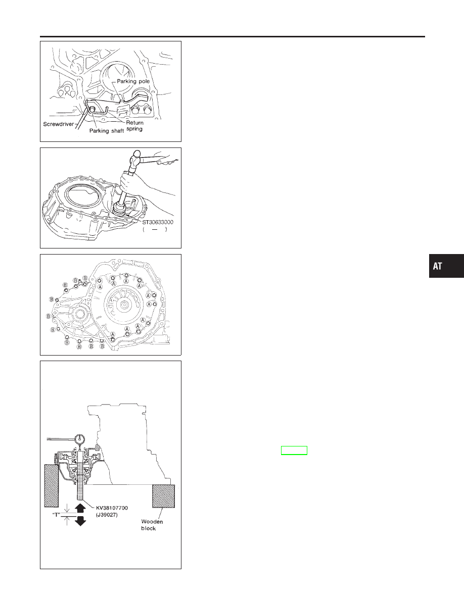
SAT330D
5.
Install return spring.
SAT947DA
Adjustment (1)
NCAT0174
DIFFERENTIAL SIDE BEARING PRELOAD
NCAT0174S01
1.
Install differential side bearing outer race without adjusting
shim on transmission case.
2.
Install differential side bearing outer race on converter housing.
SAT027D
3.
Place final drive assembly on transmission case.
4.
Install transmission case on converter housing. Tighten trans-
mission case fixing bolts A and B to the specified torque.
AAT947
5.
Attach dial indicator on differential case at transmission case
side.
6.
Insert Tool into differential side gear from converter housing.
7.
Move Tool up and down and measure dial indicator deflection.
Differential side bearing preload “T”:
0.04 - 0.09 mm (0.0016 - 0.0035 in)
8.
Select proper thickness of differential side bearing adjusting
shim(s) using SDS table as a guide.
Differential side bearing adjusting shim:
Refer to SDS, AT-394.
GI
MA
EM
LC
EC
FE
CL
MT
AX
SU
BR
ST
RS
BT
HA
SC
EL
IDX
ASSEMBLY
Assembly (1) (Cont’d)
AT-369
AAT477
9.
Remove converter housing from transmission case.
10. Remove final drive assembly from transmission case.
11. Remove differential side bearing outer race from transmission
case.
12. Reinstall differential side bearing outer race and shim(s)
selected from SDS table on transmission case.
13. Reinstall converter housing on transmission case and tighten
transmission case fixing bolts to the specified torque.
AAT466
14. Insert Tool into differential case and measure turning torque of
final drive assembly.
I
Turn final drive assembly in both directions several times
to seat bearing rollers correctly.
Turning torque of final drive assembly (New bearing):
0.49 - 1.08 N·m (5.0 - 11.0 kg-cm, 4.3 - 9.5 in-lb)
I
When old bearing is used again, turning torque will be
slightly less than the above.
I
Make sure torque is close to the specified range.
SAT876J
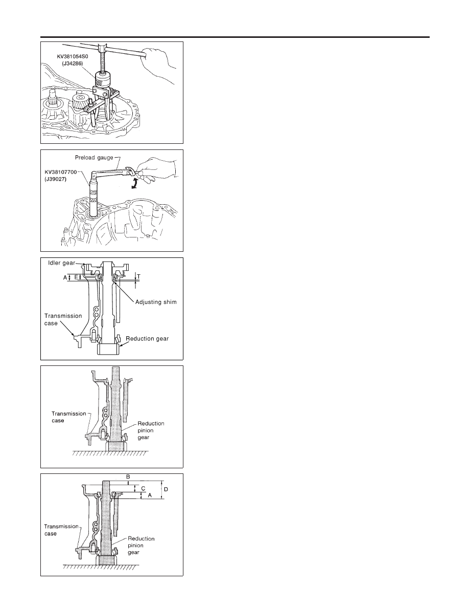
REDUCTION PINION GEAR BEARING PRELOAD
NCAT0174S02
I
Be sure to remove final drive assembly before doing this pro-
cedure.
I
Using caliper and straightedge, calculate a dimention “T”
(adjuster shim thickness) in the left figure by the following for-
mula. And adjust the inspection standard for pre-load (rotating
slide torque) as shown below.
T = A – E
Inspection standard for preload:
0.1 - 0.69 N·m (1.1 - 7.0 kg-cm, 0.95 - 6.08 in-lb)
SAT332DA
1.
Remove transmission case and final drive assembly from con-
verter housing.
2.
Select proper thickness of reduction pinion gear bearing
adjusting shim using the following procedures.
a.
Place reduction pinion gear on transmission case as shown.
SAT333DA
b.
Place idler gear bearing on transmission case.
c.
Measure dimensions “B”, “C” and “D” and calculate dimension
“A”.
A = D − (B + C)
“A”: Distance between the surface of idler gear bear-
ing inner race and the adjusting shim mating surface
of reduction pinion gear.
ASSEMBLY
Adjustment (1) (Cont’d)
AT-370
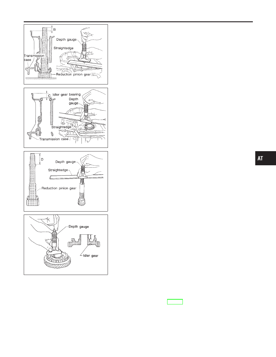
SAT334DA
I
Measure dimension “B” between the end of reduction pinion
gear and the surface of transmission case.
I
Measure dimension “B” in at least two places.
SAT335D
I
Measure dimension “C” between the surface of idler gear bear-
ing inner race and the surface of transmission case.
I
Measure dimension “C” in at least two places.
SAT336DA
I
Measure dimension “D” between the end of reduction pinion
gear and the adjusting shim mating surface of reduction pin-
ion gear.
I
Measure dimension “D” in at least two places.
I
Calculate dimension “A”.
A = D − (B + C)
SAT337D
d.
Measure dimension “E” between the end of idler gear and the
idler gear bearing inner race mating surface of idler gear.
I
Measure dimension “E” in at least two places.
e.
Calculate “T” and select proper thickness of reduction pinion
gear bearing adjusting shim using SDS table as a guide.
T = A − E – 0.05 mm (0.0020 in)*
Reduction pinion gear bearing adjusting shim:
Refer to SDS, AT-397.
*: Bearing preload
GI
MA
EM
LC
EC
FE
CL
MT
AX
SU
BR
ST
RS
BT
HA
SC
EL
IDX
ASSEMBLY
Adjustment (1) (Cont’d)
AT-371
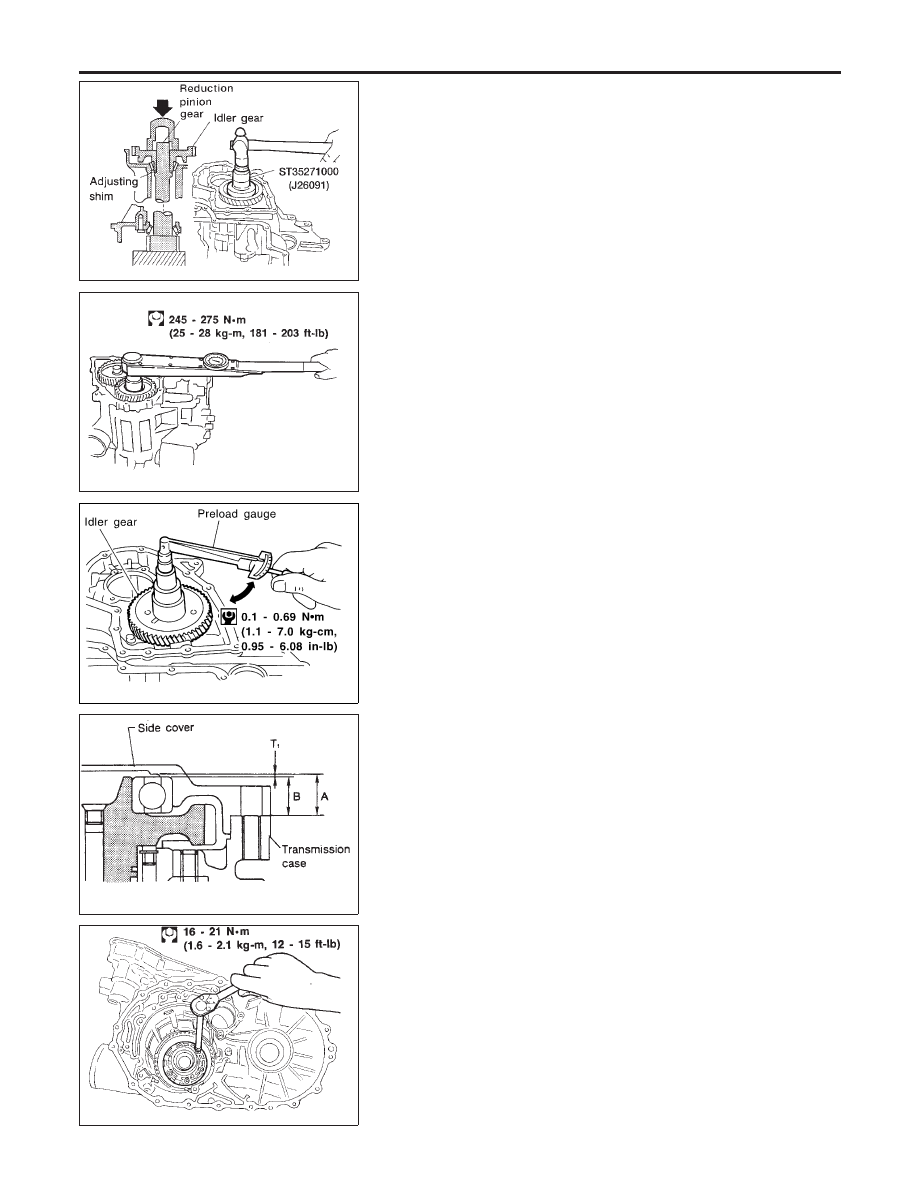
AAT696
3.
Install reduction pinion gear and reduction pinion gear bearing
adjusting shim selected in step 2-e on transmission case.
4.
Press idler gear bearing inner race on idler gear.
5.
Press idler gear on reduction pinion gear.
I
Press idler gear so that idler gear can be locked by park-
ing pawl.
SAT339D
6.
Tighten idler gear lock nut to the specified torque.
I
Lock idler gear with parking pawl when tightening lock
nut.
SAT340DC
7.
Measure turning torque of reduction pinion gear.
I
When measuring turning torque, turn reduction pinion
gear in both directions several times to seat bearing roll-
ers correctly.
Turning torque of reduction pinion gear:
0.1 - 0.69 N·m (1.1 - 7.0 kg-cm, 0.95 - 6.08 in-lb)
SAT341D
OUTPUT SHAFT END PLAY
NCAT0174S03
I
Measure clearance between side cover and the end of the
output shaft bearing.
I
Select proper thickness of adjusting shim so that clearance is
within specifications.
SAT347D
1.
Install bearing retainer for output shaft.
ASSEMBLY
Adjustment (1) (Cont’d)
AT-372
Нет комментариевНе стесняйтесь поделиться с нами вашим ценным мнением.
Текст