Infiniti G20 (P11). Manual — part 252
16
CHECK FUEL TANK TEMPERATURE SENSOR
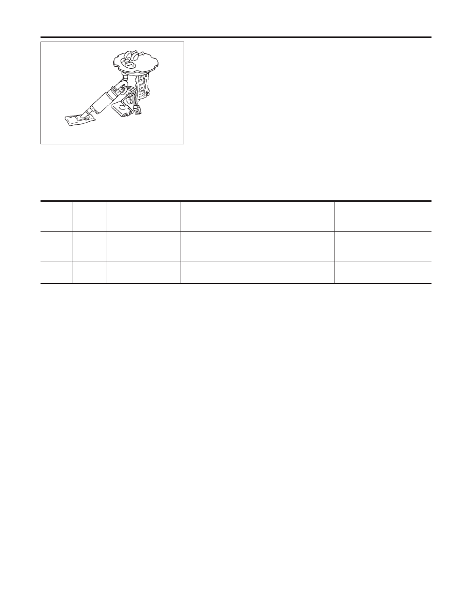
1. Remove fuel level sensor unit.
2. Check fuel tank temperature sensor.
Refer to EC-290, “Component Inspection”.
OK or NG
OK
©
GO TO 17.
NG
©
Replace fuel level sensor unit.
17
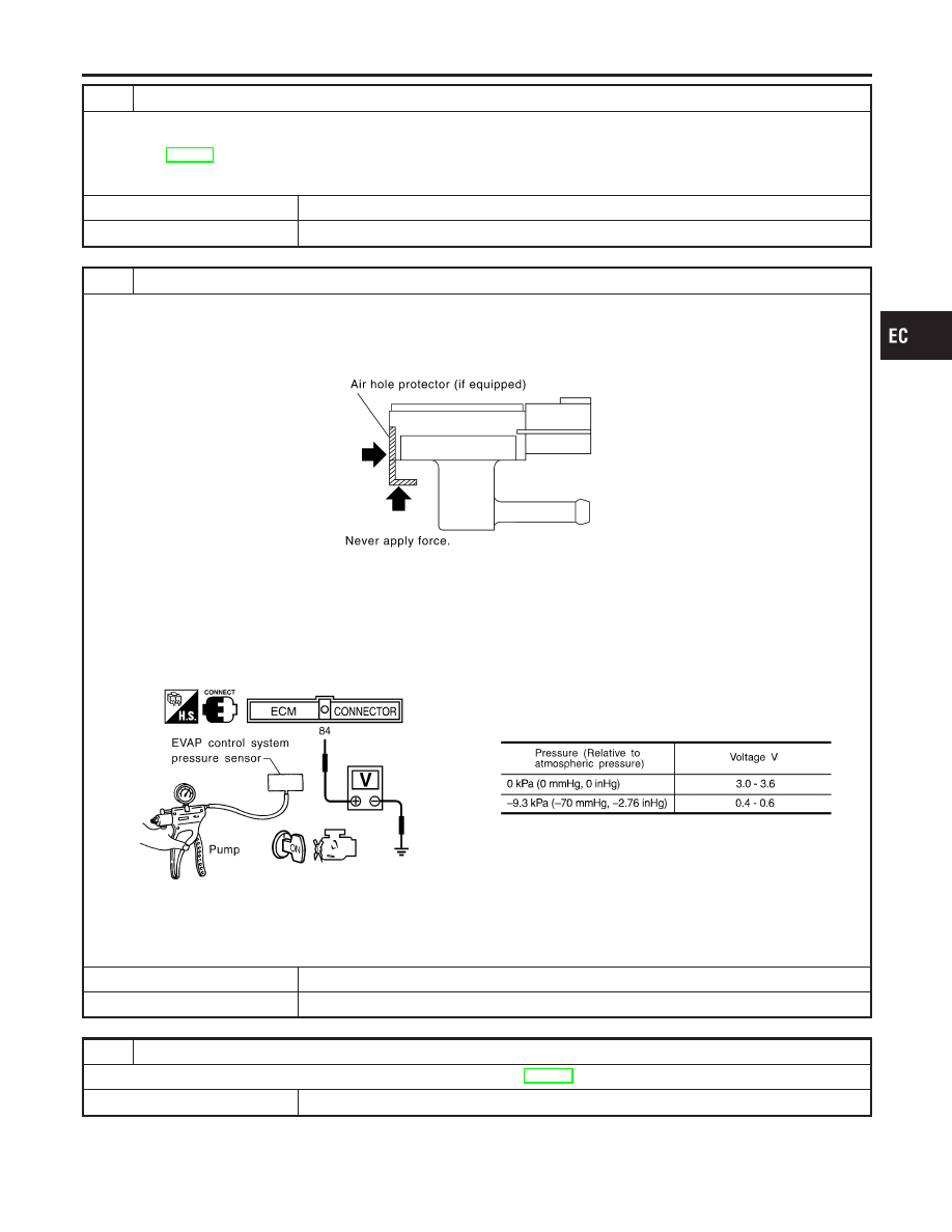
CHECK EVAP CONTROL SYSTEM PRESSURE SENSOR
1. Remove EVAP control system pressure sensor with its harness connector connected.
CAUTION:
I
Never apply force to the air hole protector of the sensor if equipped.
SEF799W
2. Remove hose from EVAP control system pressure sensor.
3. Turn ignition switch “ON”.
4. Use pump to apply vacuum and pressure to EVAP control system pressure sensor as shown in figure.
CAUTION:
I
Always calibrate the vacuum pump gauge when using it.
I
Do not apply below −20 kPa (−150 mmHg, −5.91 inHg) or over 20 kPa (150 mmHg, 5.91 inHg) of pressure.
5. Check input voltage between ECM terminal 84 and ground.
SEF342X
CAUTION:
I
Discard and EVAP control system pressure sensor which has been dropped from a height of more than 0.5
m (19.7 in) onto a hard surface such as a concrete floor; use a new one.
OK or NG
OK
©
GO TO 18.
NG
©
Replace EVAP control system pressure sensor.
18
CHECK INTERMITTENT INCIDENT
Refer to “TROUBLE DIAGNOSIS FOR INTERMITTENT INCIDENT”, EC-146.
©
INSPECTION END
GI
MA
EM
LC
FE
CL
MT
AT
AX
SU
BR
ST
RS
BT
HA
SC
EL
IDX
DTC P0455 EVAP CONTROL SYSTEM (GROSS LEAK)
Diagnostic Procedure (Cont’d)
EC-419
AEC801
Component Description
NCEC0552
The fuel level sensor is mounted in the fuel level sensor unit. The
sensor detects a fuel level in the fuel tank and transmits a signal
to the ECM.
It consists of two parts, one is mechanical float and the other side
is variable resistor. Fuel level sensor output voltage changes
depending on the movement of the fuel mechanical float.
ECM Terminals and Reference Value
NCEC0653
Specification data are reference values and are measured between each terminal and ground.
CAUTION:
Do not use ECM ground terminals when measuring input/output voltage. Doing so may result in dam-
age to the ECM’s transistor. Use a ground other than ECM terminals, such as the ground.
TERMI-
NAL
NO.
WIRE
COLOR
ITEM
CONDITION
DATA (DC Voltage)
83
G/R
Fuel level sensor
[Ignition switch “ON”]
Approximately 0 - 4.8V
Output voltage varies with fuel
level.
90
B
Fuel level sensor
ground
[Engine is running]
I
Idle speed
Approximately 0V
On Board Diagnostic Logic
NCEC0553
When the vehicle is parked, naturally the fuel level in the fuel tank
is stable. It means that output signal of the fuel level sensor does
not change. If ECM senses sloshing signal from the sensor, fuel
level sensor malfunction is detected.
Malfunction is detected when even though the vehicle is parked, a
signal being varied is sent from the fuel level sensor to ECM.
Possible Cause
NCEC0554
I
Fuel level sensor circuit
(The fuel level sensor circuit is open or shorted.)
I
Fuel level sensor
DTC P0460 FUEL LEVEL SENSOR FUNCTION (SLOSH)
Component Description
EC-420
SEF195Y
DTC Confirmation Procedure
NCEC0555
NOTE:
If “DTC Confirmation Procedure” has been previously conducted,
always turn ignition switch “OFF” and wait at least 10 seconds
before conducting the next test.
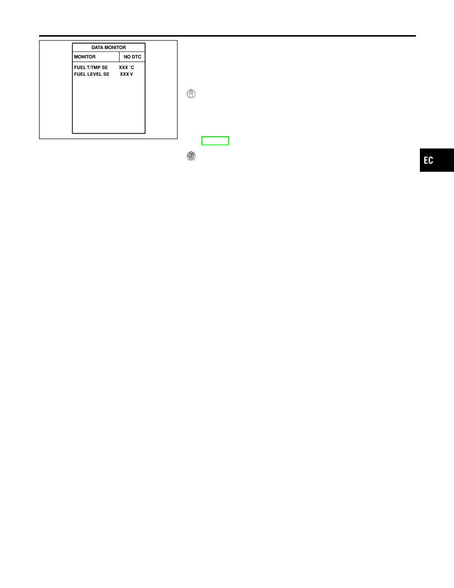
WITH CONSULT-II
NCEC0555S01
1)
Turn ignition switch “ON”.
2)
Select “DATA MONITOR” mode with CONSULT-II.
3)
Start engine and wait maximum of 2 consecutive minutes.
4)
If 1st trip DTC is detected, go to “Diagnostic Procedure”,
EC-423.
WITH GST
NCEC0555S02
Follow the procedure “WITH CONSULT-II” above.
GI
MA
EM
LC
FE
CL
MT
AT
AX
SU
BR
ST
RS
BT
HA
SC
EL
IDX
DTC P0460 FUEL LEVEL SENSOR FUNCTION (SLOSH)
DTC Confirmation Procedure
EC-421
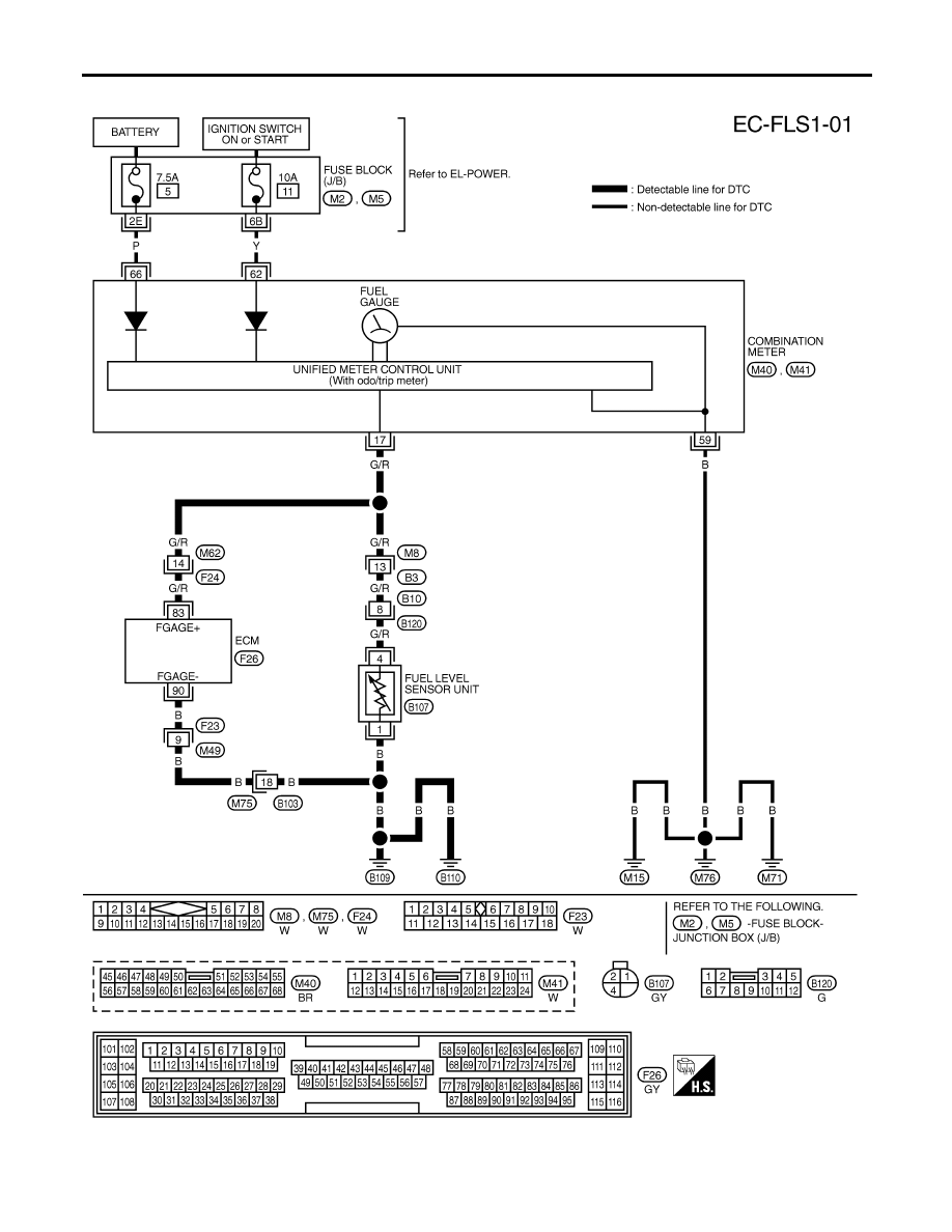
Wiring Diagram
NCEC0556
TEC829
DTC P0460 FUEL LEVEL SENSOR FUNCTION (SLOSH)
Wiring Diagram
EC-422
Нет комментариевНе стесняйтесь поделиться с нами вашим ценным мнением.
Текст