Infiniti G20 (P11). Manual — part 536
SMA525A
On-vehicle Service
REAR SUSPENSION PARTS
NCSU0029
Check axle and suspension parts for excessive play, wear or dam-
age.
I
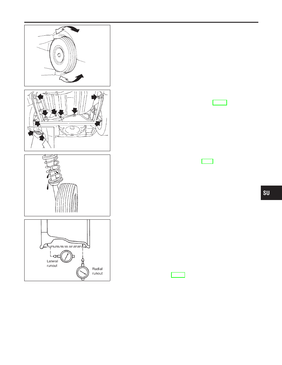
Shake each rear wheel to check for excessive play.
SRA789A
I
Retighten all nuts and bolts to the specified torque.
Tightening torque:
Refer to “REAR SUSPENSION”, SU-18.
SMA113
I
Check shock absorber for oil leakage or other damage.
I
Check wheelarch height. Refer to SU-5 (“FRONT SUSPEN-
SION PARTS”, “On-vehicle Service”).
SFA975B
REAR WHEEL ALIGNMENT
NCSU0030
Preliminary Inspection
NCSU0030S01
1.
Check tires for wear and improper inflation.
2.
Check wheels for deformation, cracks and other damage. If
deformed, remove wheel and check wheel runout.
a.
Remove tire from aluminum wheel and mount on a tire balance
machine.
b.
Set dial indicator as shown in the illustration.
Wheel runout (Dial indicator value):
Refer to SDS, SU-16.
3.
Check front wheel bearings for looseness.
4.
Check front suspension for looseness.
5.
Check steering linkage for looseness.
6.
Check that front shock absorbers work properly.
7.
Check vehicle posture (Unladen).
GI
MA
EM
LC
EC
FE
CL
MT
AT
AX
BR
ST
RS
BT
HA
SC
EL
IDX
REAR SUSPENSION
On-vehicle Service
SU-19
SFA948A
Camber
NCSU0030S02
Camber is preset at factory and cannot be adjusted.
Camber:
Refer to SDS, SU-25.
I
If the camber is not within specification, inspect and replace
any damaged or worn rear suspension parts.
SFA614B
SFA234AC
Toe-in
NCSU0030S03
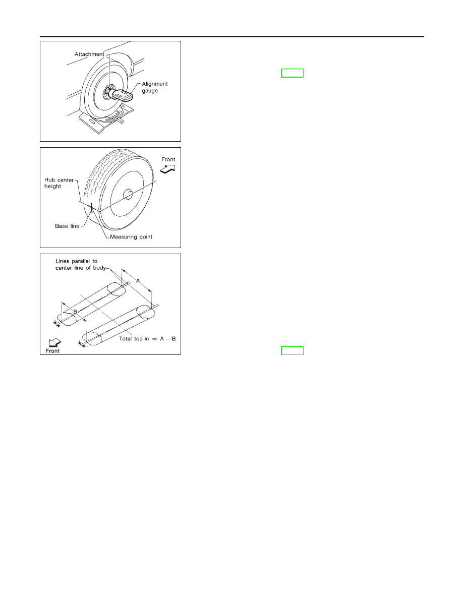
Toe-in is preset at factory and cannot be adjusted.
Measure
toe-in
using
following
procedure.
If
out
of
specification, inspect and replace any damaged or worn rear
suspension parts.
WARNING:
I
Perform following procedure always on a flat surface.
I
Make sure that no person is in front of the vehicle before
pushing it.
1.
Bounce rear of vehicle up and down to stabilize the posture.
2.
Push the vehicle straight ahead about 5 m (16 ft).
3.
Put a mark on base line of the tread (rear side) of both tires at
the same height of hub center. This mark is a measuring point.
4.
Measure distance “A” (rear side).
5.
Push the vehicle slowly ahead to rotate the wheels 180
degrees (1/2 turn).
If the wheels have rotated more than 180 degrees (1/2 turn), try
the above procedure again from the beginning. Never push
vehicle backward.
6.
Measure distance “B” (front side).
Total toe-in:
Refer to SDS, SU-25.
REAR SUSPENSION
On-vehicle Service (Cont’d)
SU-20
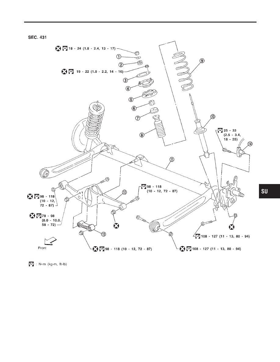
Removal and Installation
NCSU0031
SRA791AB
1.
Washer
2.
Bushing
3.
Shock absorber mounting seal
4.
Shock absorber mounting bracket
5.
Upper spring seat rubber
6.
Bushing
7.
Bound bumper cover
8.
Bound bumper
9.
Coil spring
10. Shock absorber
11. Torsion beam
12. Lateral link
13. Control rod
14. ABS sensor
GI
MA
EM
LC
EC
FE
CL
MT
AT
AX
BR
ST
RS
BT
HA
SC
EL
IDX
REAR SUSPENSION
Removal and Installation
SU-21
SRA695A
SRA792A
REMOVAL
NCSU0031S01
CAUTION:
I
Before removing the rear suspension assembly, discon-
nect the ABS wheel sensor from the assembly. Failure to
do so may result in damage to the sensor wires and the
sensor becoming inoperative.
I
Remove suspension assembly.
1.
Disconnect parking brake cable from caliper and remove brake
caliper and rotor.
Suspend caliper assembly with wire so as not to stretch brake
hose.
Be careful not to depress brake pedal, or piston will pop out.
Make sure brake hose is not twisted.
2.
Using a transmission jack, raise torsion beam a little, and
remove nuts and bolts from the trailing arm, shock absorber
assembly (lower side) and lateral link.
3.
Lower transmission jack, and remove suspension.
4.
Remove trunk room trim. Refer to BT-33, “Trunk Room”.
5.
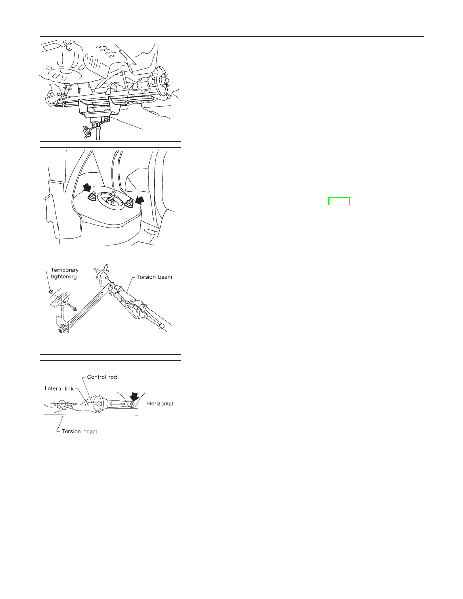
Remove strut securing nuts (upper side). Then pull out strut
assembly.
SRA697A
INSTALLATION
NCSU0031S02
I
Install suspension assembly.
CAUTION:
Refill with new brake fluid “DOT 3”.
Never reuse drained brake fluid.
1.
Attach control rod to lateral link. Do not tighten bolts at this
time.
2.
Attach lateral link, control rod and torsion beam to vehicle. Do
not tighten bolts at this time.
SRA698A
3.
Using a transmission jack to lift the torsion beam, place lateral
link and control rod horizontally against torsion beam. Tighten
bolts and nuts to specified torque.
4.
Attach shock absorber assembly to vehicle. Then tighten the
upper side of shock absorber assembly.
5.
Remove transmission jack and lower torsion beam so that the
shock absorber assembly reaches full extension. Tighten tor-
sion beam at trailing arm and lower side of shock absorber
assembly to specified torque.
Coil Spring and Shock Absorber
REMOVAL
NCSU0032
Remove shock absorber upper and lower fixing nuts.
Do not remove piston rod lock nut on vehicle.
REAR SUSPENSION
Removal and Installation (Cont’d)
SU-22
Нет комментариевНе стесняйтесь поделиться с нами вашим ценным мнением.
Текст