Infiniti G20 (P11). Manual — part 485
SMT563A
Replacing Oil Seal
NCMT0005
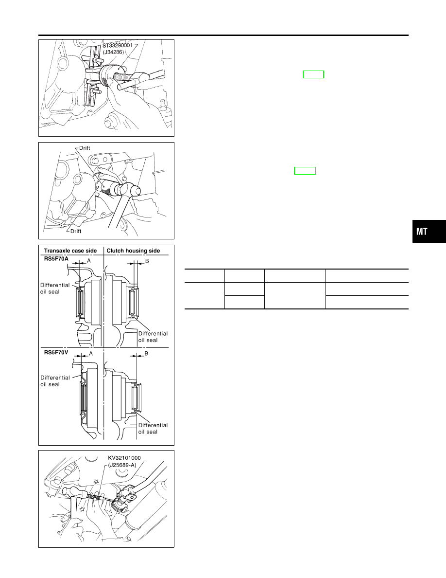
DIFFERENTIAL OIL SEAL
NCMT0005S01
1.
Drain gear oil from transaxle.
2.
Remove drive shafts. Refer to AX-11, “Removal”.
3.
Remove differential oil seal.
SMT126DB
4.
Install differential oil seal.
I
Apply multi-purpose grease to seal lip of oil seal before
installing.
5.
Install drive shafts. Refer to AX-12, “Installation”.
SMT903D
I
Install differential oil seal so that dimension “A” and “B”
are within specifications.
Unit: mm (in)
Item
Model
A
B
Dimension
RS5F70A
0.5 (0.020) or less
5.5 - 6.5 (0.217 - 0.256)
RS5F70V
0.5 (0.020) or less
SMT143DB
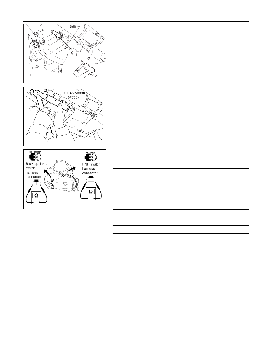
STRIKING ROD OIL SEAL
NCMT0005S02
1.
Remove transaxle control rod from yoke.
2.
Remove retaining pin of yoke.
I
Be careful not to damage boot.
GI
MA
EM
LC
EC
FE
CL
AT
AX
SU
BR
ST
RS
BT
HA
SC
EL
IDX
ON-VEHICLE SERVICE
Replacing Oil Seal
MT-9
SMT566A
3.
Remove striking rod oil seal.
SMT570AA
4.
Install striking rod oil seal.
I
Apply multi-purpose grease to seal lip of oil seal before
installing.
SMT715BD
Position Switch Check
NCMT0006
BACK-UP LAMP SWITCH
NCMT0006S01
I
Check continuity.
Gear position
Continuity
Reverse
Yes
Except reverse
No
PNP SWITCH
NCMT0006S02
I
Check continuity.
Gear position
Continuity
Neutral
Yes
Except neutral
No
ON-VEHICLE SERVICE
Replacing Oil Seal (Cont’d)
MT-10
SMT628D
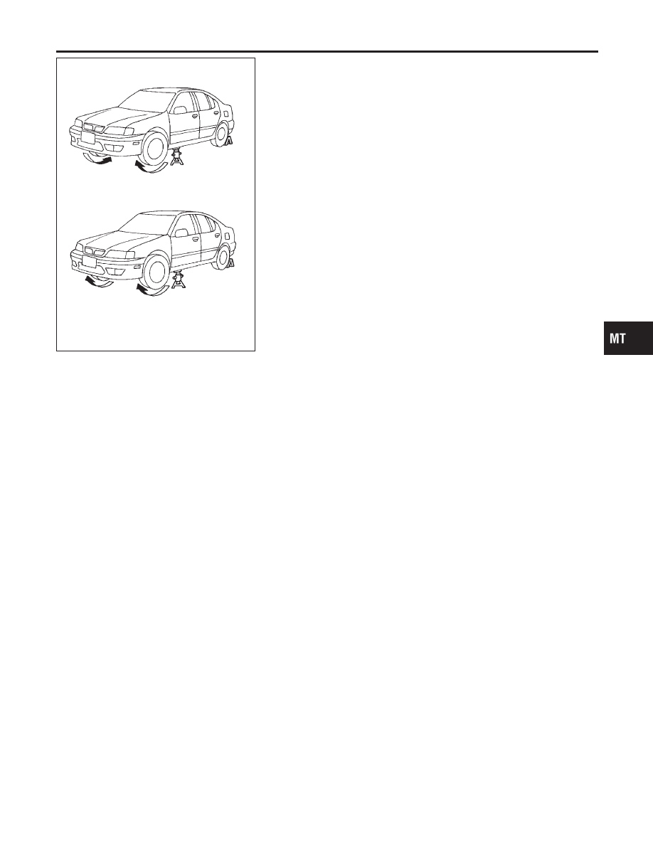
Viscous Coupling Check
NCMT0039
1.
Apply parking brake firmly and place shift lever in the neutral
position.
2.
Jack up front wheels.
3.
Rotate one front wheel and check turning direction of the other
front wheel.
Turning direction of the two wheels is opposite:
The viscous coupling is not functioning normally.
Turning direction of the two wheels is the same:
If differential side gear and pinion mate gear thrust washers are
OK, viscous coupling is functioning normally.
GI
MA
EM
LC
EC
FE
CL
AT
AX
SU
BR
ST
RS
BT
HA
SC
EL
IDX
ON-VEHICLE SERVICE
Viscous Coupling Check
MT-11
NCMT0007
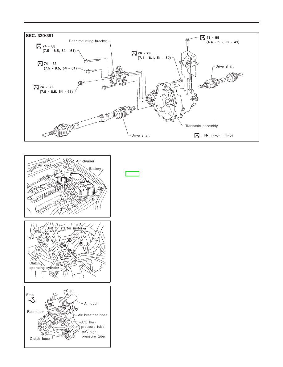
Removal
NCMT0007S01
SMT137D
SMT129D
1.
Remove battery negative terminal.
2.
Remove air cleaner and air duct.
3.
Remove clutch operating cylinder from transaxle. Refer to
CL-13, “Removal”.
4.
Disconnect back-up lamp switch, speedometer sensor, PNP
switch and ground harness connectors.
SMT130D
5.
Remove starter motor from transaxle.
SMT132D
6.
Remove air bleeder hose.
REMOVAL AND INSTALLATION
Removal
MT-12
Нет комментариевНе стесняйтесь поделиться с нами вашим ценным мнением.
Текст