Infiniti G20 (P11). Manual — part 472
ENGINE LUBRICATION &
COOLING SYSTEMS
CONTENTS
ENGINE LUBRICATION SYSTEM. . . . . . . . ..2
Precautions . . . . . . . . . . . . . . . . ..2
LIQUID GASKET APPLICATION PROCEDURE
. . . 2
Preparation . . . . . . . . . . . . . . . . ..2
. . . . . . . . . . 2
Lubrication Circuit . . . . . . . . . . . . . . 3
Oil Pressure Check. . . . . . . . . . . . . ..4
Oil Pump . . . . . . . . . . . . . . . . . ..4
. . . . . . . . . . . . . . . . .4
. . . . . . . . . . . . . . . .5
. . . . . . . 6
. . . . . . . . . . . . . . ..7
Oil Filter . . . . . . . . . . . . . . . . . ...7
Service Data and Specifications (SDS). . . . . ...7
. . . . . . . . . . . 7
. . . . . . . 7
. . . . . . . . . . . 7
ENGINE COOLING SYSTEM. . . . . . . . . . ..8
Precautions . . . . . . . . . . . . . . . . ..8
LIQUID GASKET APPLICATION PROCEDURE
. . . 8
Preparation . . . . . . . . . . . . . . . . ..8
. . . . . . . . . . ..8
Cooling Circuit . . . . . . . . . . . . . . . .9
System Check. . . . . . . . . . . . . . . ..9
. . . . . .9
CHECKING COOLING SYSTEM FOR LEAKS
. . . ..9
. . . . . . . . . . . 10
. . . . . . . . . 10
Water Pump . . . . . . . . . . . . . . . ...10
. . . . . . . . . . . . . . . ...10
. . . . . . . . . . . . . . ... 11
. . . . . . . . . . . . . . 11
Thermostat. . . . . . . . . . . . . . . . .12
. . . . . . . ...12
. . . . . . . . . . . . . . ...13
Water Outlet. . . . . . . . . . . . . . . ...13
. . . . . . . . . . . . . . ...13
. . . . . . . . . . . . . . 13
Radiator . . . . . . . . . . . . . . . . . .14
. . . . . . . . . . . . . ...14
Cooling Fan Control System . . . . . . . . . .14
Refilling Engine Coolant . . . . . . . . . . . 15
Overheating Cause Analysis . . . . . . . . . .15
Service Data and Specifications (SDS). . . . . .16
. . . . . . . . . . . . . . 16
. . . . . . . . . . . . . . . ..16
GI
MA
EM
EC
FE
CL
MT
AT
AX
SU
BR
ST
RS
BT
HA
SC
EL
IDX
SEM164F
AEM080
Precautions
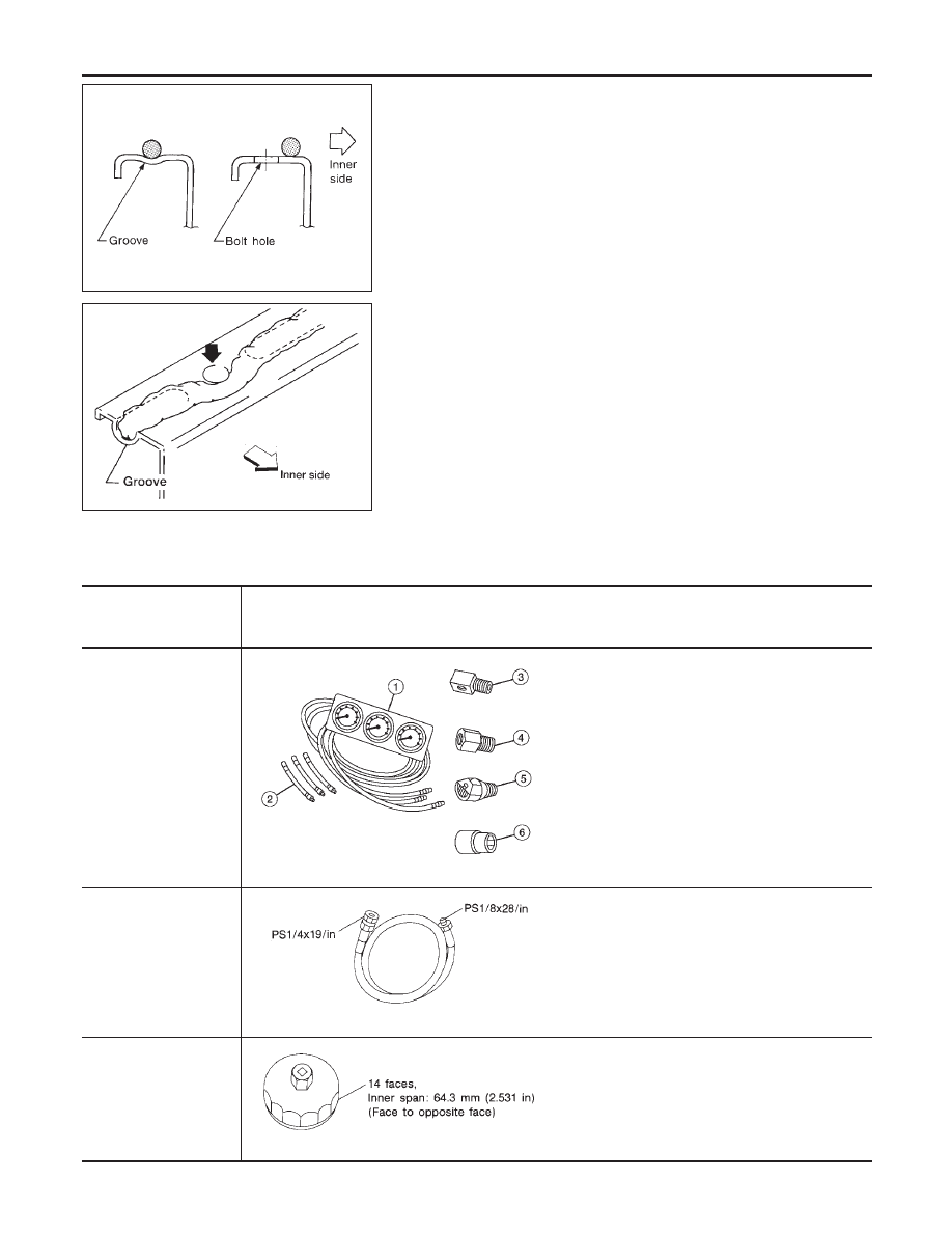
LIQUID GASKET APPLICATION PROCEDURE
NCLC0001
1.
Use a scraper to remove all traces of old liquid gasket from
mating surfaces and grooves. Also, completely clean any oil
from these areas.
2.
Apply a continuous bead of liquid gasket to mating surfaces.
(Use Genuine RTV silicone sealant part No. 999MP-A7007
or equivalent.)
I
For oil pan, be sure liquid gasket diameter is 4.0 to 5.0 mm
(0.157 to 0.197 in).
I
For areas except oil pan, be sure liquid gasket diameter is 2.0
to 3.0 mm (0.079 to 0.118 in).
3.
Apply liquid gasket around the inner side of bolt holes (unless
otherwise specified).
4.
Assembly should be done within 5 minutes after coating.
5.
Wait at least 30 minutes before refilling engine oil and engine
coolant.
Preparation
SPECIAL SERVICE TOOLS
NCLC0002
The actual shapes of Kent-Moore tools may differ from those of special service tools illustrated here.
Tool number
(Kent-Moore No.)
Tool name
Description
(J34301-C)
Oil pressure gauge set
1 (J34301-1)
Oil Pressure gauge
2 (J34301-2)
Hoses
3 (J34298)
Adapter
4 (J34282-1)
Adapter
5 (790-301-1230-A)
60° adapter
6 (J34301-15)
Square socket
AAT896
Measuring oil pressure
Maximum measuring range:
1,379 kPa (14 kg/cm
2
, 200 psi)
ST25052000
(J25695-2)
Hose
NT559
Adapting oil pressure gauge to cylinder block
KV10115801
(J38956)
Oil filter wrench
NT362
Removing oil filter
ENGINE LUBRICATION SYSTEM
Precautions
LC-2
Tool number
(Kent-Moore No.)
Tool name
Description
WS39930000
(
—
)
Tube presser
NT052
Pressing the tube of liquid gasket
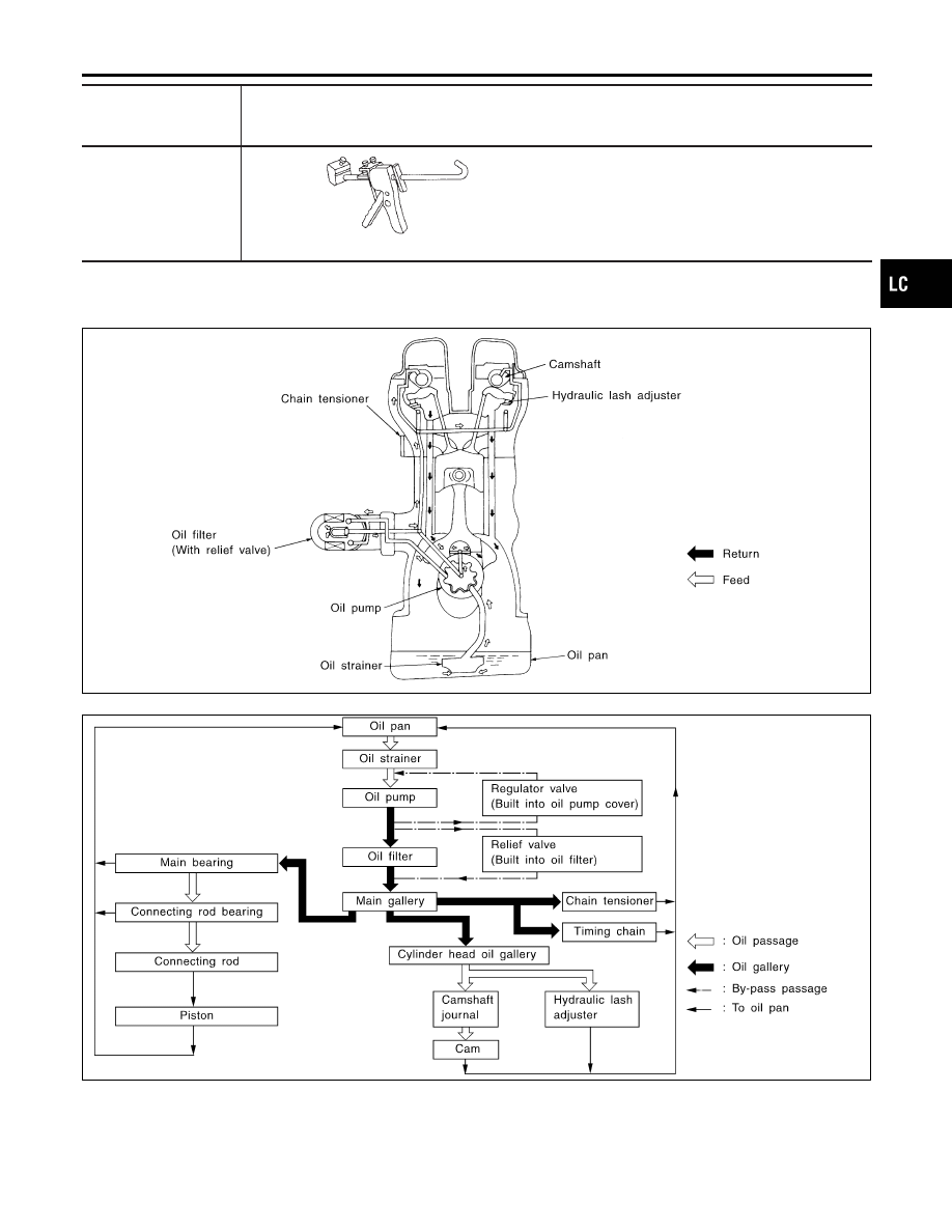
Lubrication Circuit
NCLC0003
JLC263B
SLC273B
GI
MA
EM
EC
FE
CL
MT
AT
AX
SU
BR
ST
RS
BT
HA
SC
EL
IDX
ENGINE LUBRICATION SYSTEM
Preparation (Cont’d)
LC-3
SLC264B
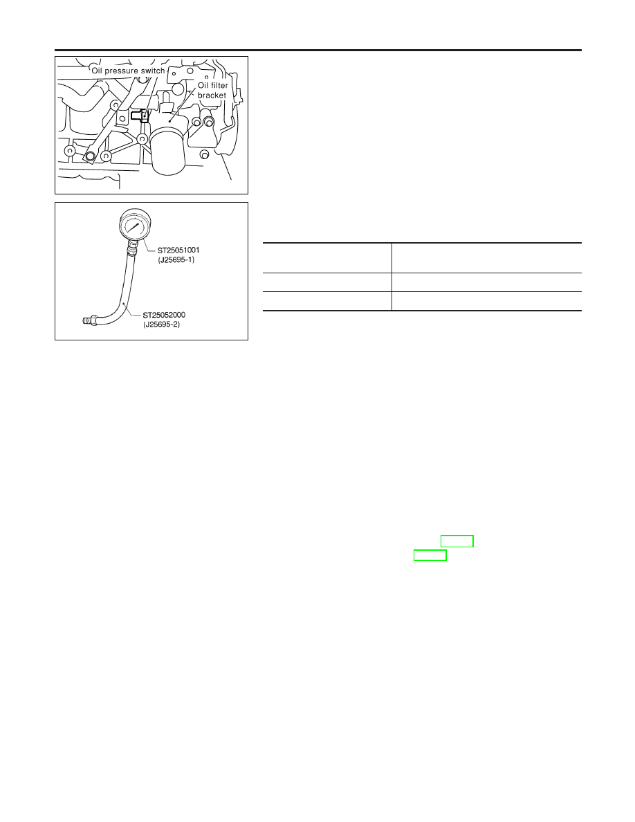
Oil Pressure Check
NCLC0004
WARNING:
I
Be careful not to burn yourself, as the engine and oil may
be hot.
I
For M/T models, put gearshift lever in Neutral “N” posi-
tion. For A/T models, put selector lever in Park “P” posi-
tion.
1.
Check oil level.
2.
Remove oil pressure switch.
SLC926
3.
Install pressure gauge.
4.
Start engine and warm it up to normal operating temperature.
5.
Check oil pressure with engine running under no-load.
Engine speed
rpm
Approximate discharge pressure
kPa (kg/cm
2
, psi)
Idle speed
More than 80 (0.82, 11.7)
3,200
314 - 392 (3.2 - 4.0, 46 - 57)
I
If difference is extreme, check oil passage and oil pump
for oil leaks.
6.
Install oil pressure switch with sealant.
Oil Pump
REMOVAL
NCLC0005
1.
Remove drive belts.
2.
Remove cylinder head. Refer to EM-31, “Removal”.
3.
Remove oil pans. Refer to EM-14, “Removal”.
4.
Remove oil strainer and baffle plate.
5.
Remove front cover assembly.
ENGINE LUBRICATION SYSTEM
Oil Pressure Check
LC-4
Нет комментариевНе стесняйтесь поделиться с нами вашим ценным мнением.
Текст