Infiniti G20 (P11). Manual — part 321
System Description
NCEL0027
OUTLINE
NCEL0027S02
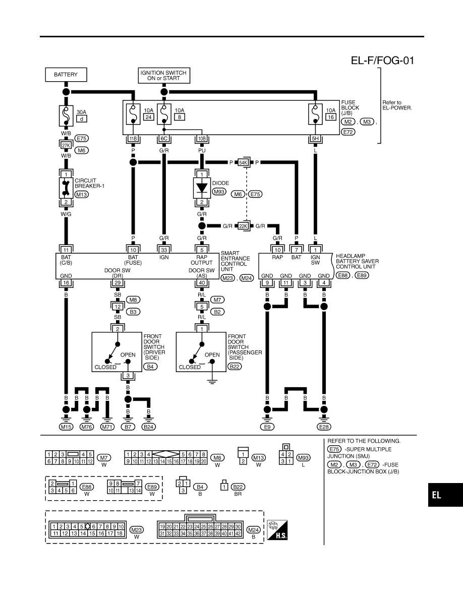
Power is supplied at all times
I
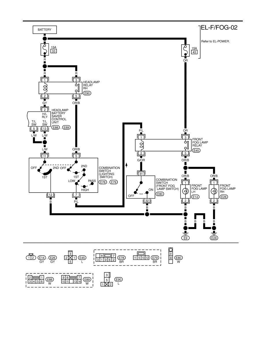
to headlamp RH relay terminals 1 and 3
I
through 15A fuse (No. 33, located in the fuse and fusible link box), and
I
to headlamp battery saver control unit terminal 7
I
through 10A fuse [No. 24, located in the fuse block (J/B)], and
I
to front fog lamp relay terminal 3
I
through 15A fuse (No. 43, located in the fuse and fusible link box).
When ignition switch is in ON or START position, power is supplied
I
to headlamp battery saver control unit terminal 1
I
through 10A fuse [No. 16, located in the fuse block (J/B)], and
I
to headlamp battery saver control unit terminal 10, and
I
to smart entrance control unit terminal 33
I
through 10A fuse [No. 8, located in the fuse block (J/B)].
Ground is supplied to headlamp battery saver control unit terminals 4 and 11.
When Ignition Switch is in ON or START Position
NCEL0027S0201
Ground is supplied
I
to headlamp RH relay terminal 2 from headlamp battery saver control unit terminal 2.
I
through headlamp battery saver control unit terminal 9, and
I
through body grounds E9 and E28.
Headlamp RH relay is then energized.
When Ignition Switch is in OFF or ACC Position
NCEL0027S0202
When lighting switch is in 2ND (or 1ST) position, ground is supplied
I
to headlamp battery saver control unit terminals 5 and 13
I
from lighting switch terminal 11.
And then, ground is also supplied to headlamp RH relay terminal 2 from the headlamp battery saver control
unit. The headlamp RH relay is then energized.
FOG LAMP OPERATION
NCEL0027S01
The fog lamp switch is built into the combination switch. The lighting switch must be in the 2ND position and
LOW (“B”) position for fog lamp operation.
With the fog lamp switch in the ON position, ground is supplied
I
to fog lamp relay terminal 2
I
through the fog lamp switch and body grounds E9 and E28.
The fog lamp relay is energized and power is supplied
I
from fog lamp relay terminal 5
I
to terminal 1 of each fog lamp.
Ground is supplied to terminal 2 of each fog lamp through body grounds E9 and E28.
With power and ground supplied, the fog lamps illuminate.
BATTERY SAVER CONTROL
NCEL0027S03
When the ignition switch is turned from ON (or START) to OFF (or ACC) positions while fog lamps are
illuminated, the RAP signal is supplied to terminal 10 of the headlamp battery saver control unit from smart
entrance control unit terminal 5.
After counting 45 seconds by the RAP signal from the smart entrance control unit to headlamp battery saver
control unit, the ground supply to terminal 2 of headlamp RH relay from headlamp battery saver control unit
teminal 2 is terminated.
Then fog lamps are turned to off.
Fog lamps are turned off when driver or passenger side door is opened even if 45 seconds have not passed
after the ignition switch is turned from ON (or START) to OFF (or ACC) positions while fog lamps are illumi-
nated.
When the lighting switch is turned from OFF to 2ND after fog lamps are turned off by the battery saver control,
ground is supplied
GI
MA
EM
LC
EC
FE
CL
MT
AT
AX
SU
BR
ST
RS
BT
HA
SC
IDX
FRONT FOG LAMP
System Description
EL-61
I
to headlamp battery saver control unit terminals 5 and 13 from lighting switch terminal 11, and
I
to headlamp RH relay terminal 2 from headlamp battery saver control unit terminal 2.
Then the fog lamps illuminate again.
FRONT FOG LAMP
System Description (Cont’d)
EL-62
Wiring Diagram — F/FOG —
NCEL0028
TEL840B
GI
MA
EM
LC
EC
FE
CL
MT
AT
AX
SU
BR
ST
RS
BT
HA
SC
IDX
FRONT FOG LAMP
Wiring Diagram — F/FOG —
EL-63
TEL490B
FRONT FOG LAMP
Wiring Diagram — F/FOG — (Cont’d)
EL-64
Нет комментариевНе стесняйтесь поделиться с нами вашим ценным мнением.
Текст