Infiniti G20 (P11). Manual — part 302
SEF855X
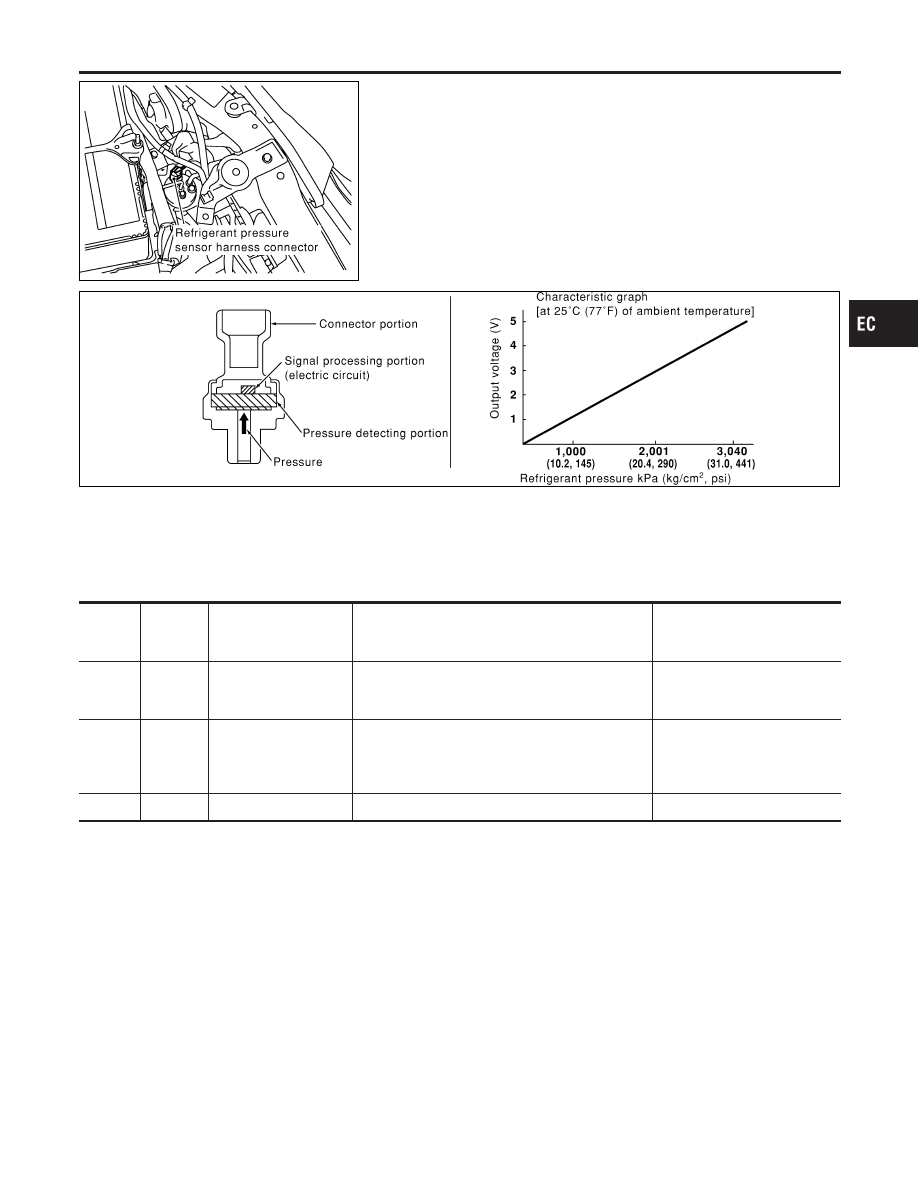
Description
NCEC0638
The refrigerant pressure sensor is installed at the liquid tank of the
air conditioner system. The sensor uses an electrostatic volume
pressure transducer to convert refrigerant pressure to voltage. The
voltage signal is sent to ECM, and ECM controls cooling fan sys-
tem.
SEF099XA
ECM Terminals and Reference Value
NCEC0663
Specification data are reference values and are measured between each terminal and ground.
CAUTION:
Do not use ECM ground terminals when measuring input/output voltage. Doing so may result in dam-
age to the ECM’s transistor. Use a ground other than ECM terminals, such as the ground.
TERMI-
NAL
NO.
WIRE
COLOR
ITEM
CONDITION
DATA (DC Voltage)
58
B
Sensor’s ground
[Engine is running]
I
Warm-up condition
I
Idle speed
Approximately 0V
74
R/L
Refrigerant pressure
sensor
[Engine is running]
I
Warm-up condition
I
Both A/C switch and blower switch are “ON”
(Compressor operates.)
0.36 - 3.88V
111
P/L
Sensor’s power supply
[Ignition switch “ON”]
Approximately 5V
GI
MA
EM
LC
FE
CL
MT
AT
AX
SU
BR
ST
RS
BT
HA
SC
EL
IDX
REFRIGERANT PRESSURE SENSOR
Description
EC-619
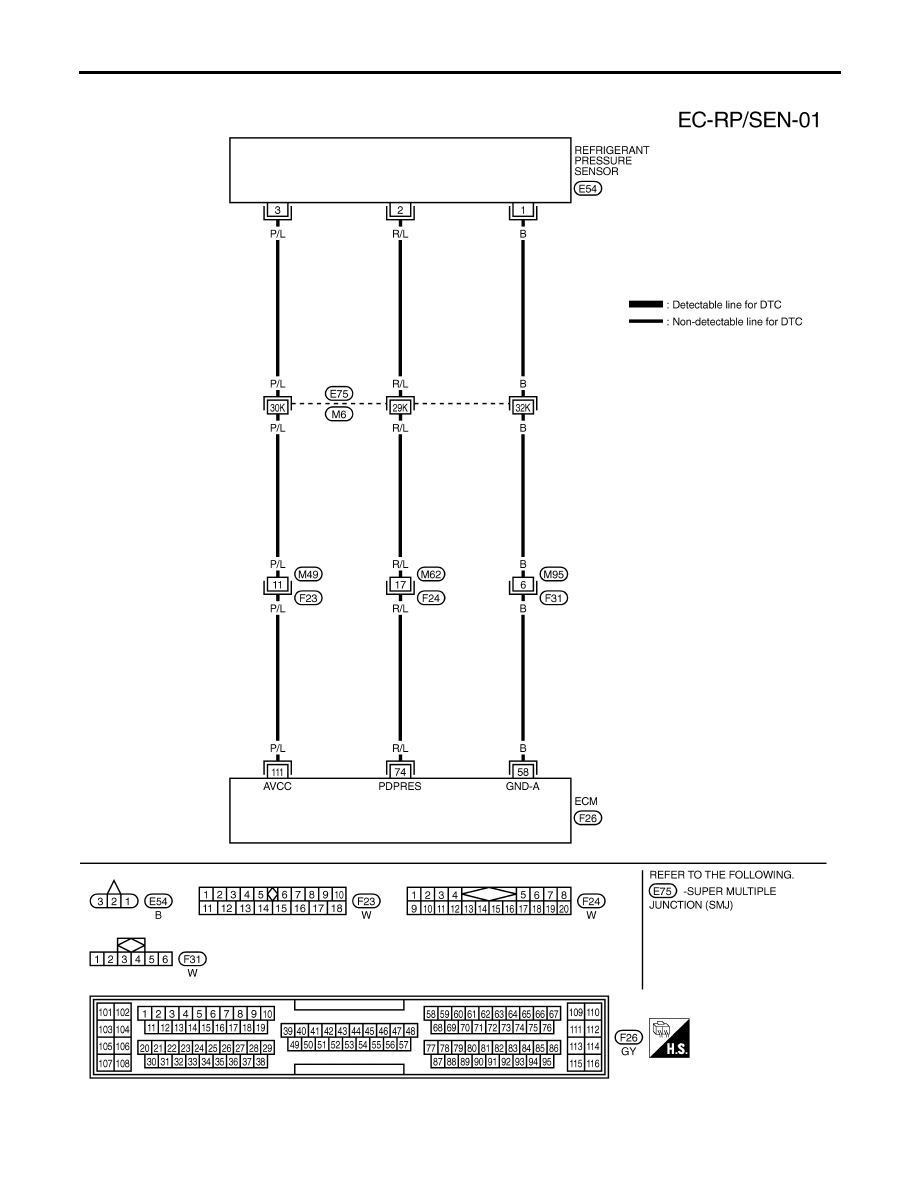
Wiring Diagram
NCEC0639
TEC733
REFRIGERANT PRESSURE SENSOR
Wiring Diagram
EC-620
Diagnostic Procedure
NCEC0640
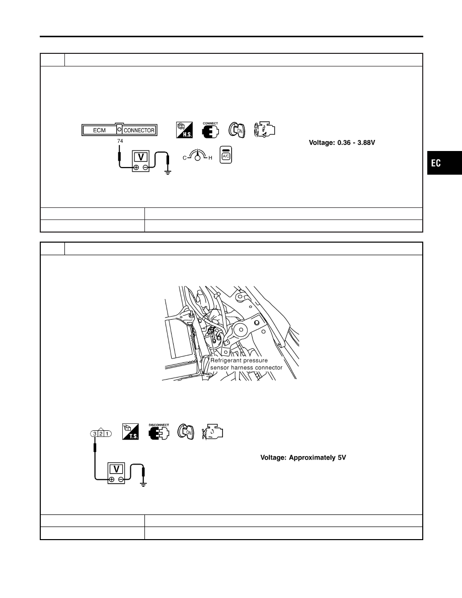
1
CHECK REFRIGERANT PRESSURE SENSOR OVERALL FUNCTION
1. Start engine and warm it up to normal operating temperature.
2. Turn A/C switch and blower switch “ON”.
3. Check voltage between ECM terminal 74 and ground with CONSULT-II or tester.
SEF952X
OK or NG
OK
©
INSPECTION END
NG
©
GO TO 2.
2
CHECK REFRIGERANT PRESSURE SENSOR POWER SUPPLY CIRCUIT
1. Turn A/C switch and blower switch “OFF”.
2. Stop engine.
3. Disconnect refrigerant pressure sensor harness connector.
SEF855X
4. Turn ignition switch “ON”.
5. Check voltage between refrigerant pressure sensor terminal 3 and ground with CONSULT-II or tester.
SEF953X
OK or NG
OK
©
GO TO 4.
NG
©
GO TO 3.
GI
MA
EM
LC
FE
CL
MT
AT
AX
SU
BR
ST
RS
BT
HA
SC
EL
IDX
REFRIGERANT PRESSURE SENSOR
Diagnostic Procedure
EC-621

3
DETECT MALFUNCTIONING PART
Check the following.
I
Harness connectors E75, M6
I
Harness connectors M49, F23
I
Harness for open or short between ECM and refrigerant pressure sensor
©
Repair harness or connectors.
4
CHECK REFRIGERANT PRESSURE SENSOR GROUND CIRCUIT FOR OPEN AND SHORT
1. Turn ignition switch “OFF”.
2. Check harness continuity between refrigerant pressure sensor terminal 1 and engine ground. Refer to Wiring Diagram.
Continuity should exist.
3. Also check harness for short to power.
OK or NG
OK
©
GO TO 6.
NG
©
GO TO 5.
5
DETECT MALFUNCTIONING PART
Check the following.
I
Harness connectors E75, M6
I
Harness connectors M95, F31
I
Harness for open or short between ECM and refrigerant pressure sensor
©
Repair open circuit or short to power in harness or connectors.
6
CHECK REFRIGERANT PRESSURE SENSOR INPUT SIGNAL CIRCUIT FOR OPEN AND SHORT
1. Disconnect ECM harness connector.
2. Check harness continuity between ECM terminal 74 and refrigerant pressure sensor terminal 2. Refer to Wiring Dia-
gram.
Continuity should exist.
3. Also check harness for short to ground and short to power.
OK or NG
OK
©
GO TO 8.
NG
©
GO TO 7.
7
DETECT MALFUNCTIONING PART
Check the following.
I
Harness connectors E75, M6
I
Harness connectors M62, F24
I
Harness for open or short between ECM and refrigerant pressure sensor
©
Repair open circuit or short to ground or short to power in harness or connectors.
8
CHECK REFRIGERANT PRESSURE SENSOR
Refer to HA-79 or HA-181, “Refrigerant pressure sensor”.
OK or NG
OK
©
GO TO 9.
NG
©
Replace refrigerant pressure sensor.
REFRIGERANT PRESSURE SENSOR
Diagnostic Procedure (Cont’d)
EC-622
Нет комментариевНе стесняйтесь поделиться с нами вашим ценным мнением.
Текст