Infiniti G20 (P11). Manual — part 495
SMT736D
15. Install differential assembly, input shaft assembly, and main-
shaft assembly into clutch housing.
CAUTION:
Be careful not to damage input shaft oil seal during installa-
tion of input shaft assembly.
SMT659DB
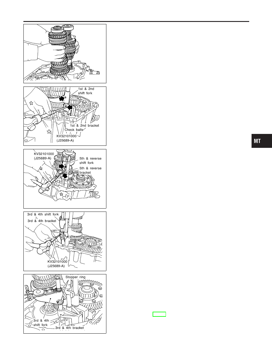
16. Install 5th & reverse shift fork.
17. Install 1st & 2nd shift fork, bracket, and fork rod.
18. Install retaining pin for 1st & 2nd bracket.
CAUTION:
Do not reuse retaining pin.
19. Install two check balls.
SMT657DB
20. Install interlock pin into 5th & reverse fork rod.
21. Install reverse switch bracket, 5th & reverse bracket, and fork
rod.
22. Install retaining pin for 5th & reverse shift fork and reverse
switch bracket.
CAUTION:
Do not reuse retaining pin.
23. Install 5th & reverse bracket stopper ring.
CAUTION:
Do not reuse stopper pin.
SMT656DB
24. Install check ball and interlock plunger.
25. Install 3rd & 4th shift fork, bracket, and fork rod.
26. Install 3rd & 4th bracket retaining pin.
CAUTION:
Do not reuse retaining pin.
SMT655D
27. Install 3rd & 4th shift fork stopper ring.
CAUTION:
Do not reuse stopper ring.
28. Install check ball, check pin, and check spring, and apply
Three Bond TB1215, Loctite Part No. 51813 or equivalent onto
check plug. Then, tighten it with specified torque.
Tightening torque:
Refer to MT-18.
GI
MA
EM
LC
EC
FE
CL
AT
AX
SU
BR
ST
RS
BT
HA
SC
EL
IDX
ASSEMBLY
Clutch Housing (Cont’d)
MT-49
SMT737DA
Transaxle Case
NCMT0023S02
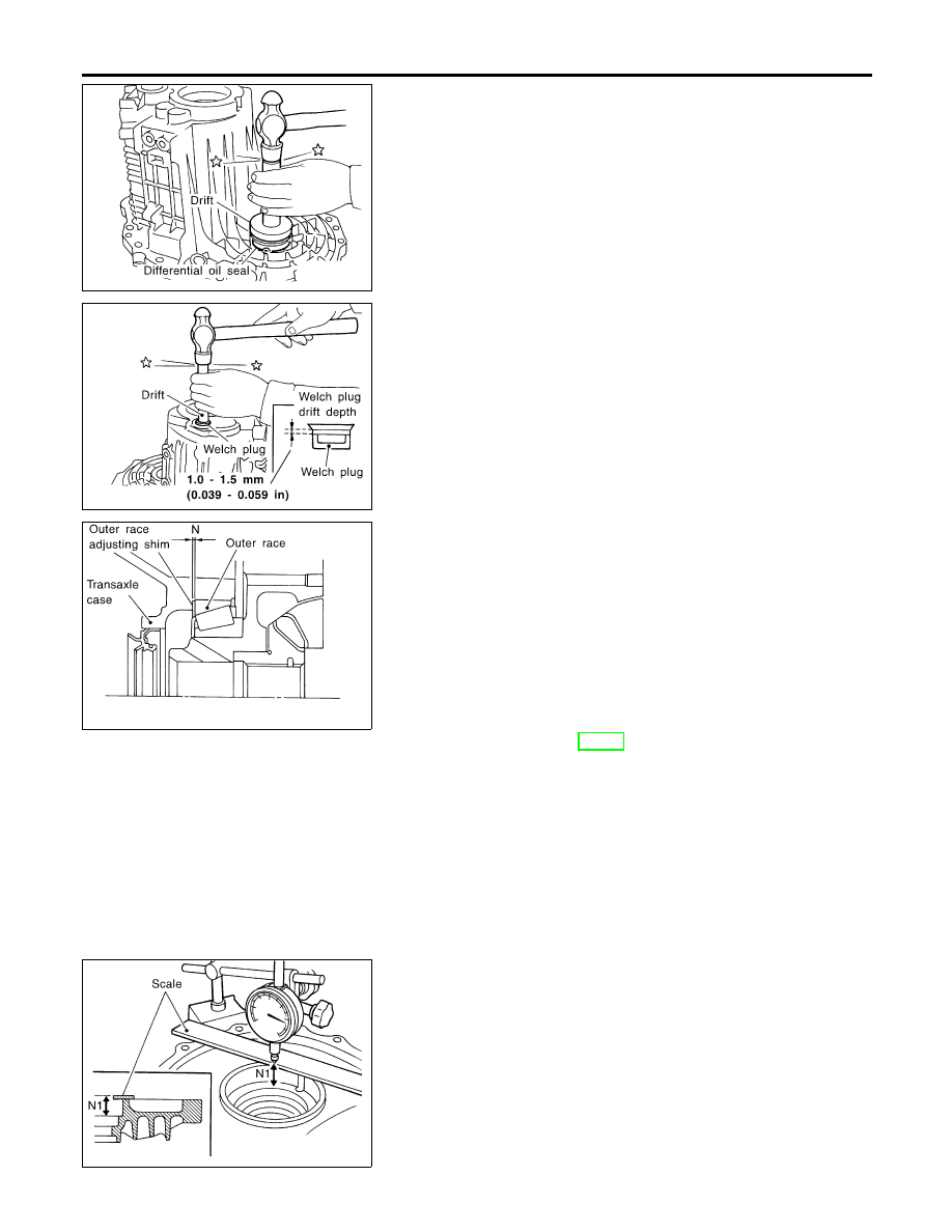
1.
Insert differential oil seal into differential case until it becomes
flush with case end face.
SMT739D
2.
Install welch plug into transaxle case.
SMT740D
3.
Calculate dimension “N” (thickness of adjusting shim) using
the following procedure to satisfy specification of end play for
differential side bearing.
End play: 0.15 - 0.21 mm (0.0059 - 0.0083 in)
Dimension “N” = (N1 – N2) + End play
N: Thickness of adjusting shim
N1: Distance between clutch housing case end
face and mounting face of adjusting shim
N2: Distance between differential side bearing and
transaxle case
Differential side bearing adjusting shims:
Refer to SDS, MT-62.
SMT741D
a.
Using dial gauge and scale, measure dimension “N1” between
clutch housing case end face and mounting face of adjusting
shim.
ASSEMBLY
Transaxle Case
MT-50
SMT742D
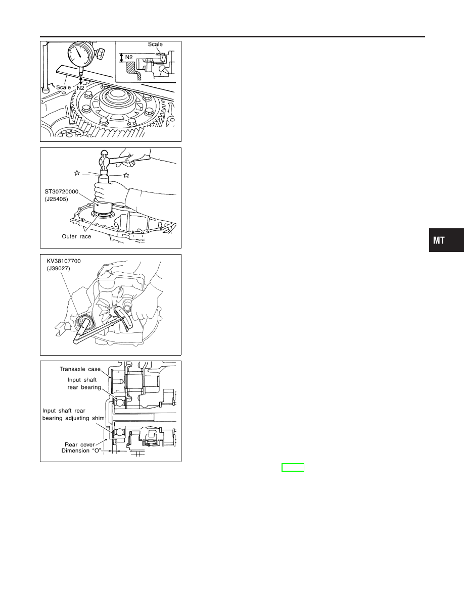
b.
Install outer race onto differential side bearing on final gear
side. Holding lightly the outer race horizontally by hand, rotate
final gear five times or more (for smooth movement of bearing
roller).
c.
Using dial gauge and scale as shown in the figure, measure
dimension “N2” between differential side bearing outer race
and transaxle case end face.
SMT738DA
4.
Install selected shim and bearing outer race.
SMT600-E
5.
Measure turning torque of final drive assembly.
Turning torque of final drive assembly
(New bearing):
2.9 - 6.9 N·m (30 - 70 kg-cm, 26 - 61 in-lb)
I
When old bearing is used again, turning torque will be
slightly less than the above.
I
Make sure torque is close to the specified range.
I
Changes in turning torque of final drive assembly per
revolution should be within 1.0 N·m (10 kg-cm, 8.7 in-lb)
without binding.
SMT743D
6.
Calculate dimension “O” (thickness of adjusting shim) using
the following procedure to satisfy specification of end play for
input shaft rear bearing.
End play: 0 - 0.06 mm (0 - 0.0024 in)
Dimension “O” = (O1 – O2) + End play
O: Thickness of adjusting shim
O1: Distance between transaxle case end face and
mounting face of adjusting shim
O2: Distance between clutch housing case end
face and end face of input shaft rear bearing
Input shaft rear bearing adjusting shims:
Refer to SDS, MT-59.
GI
MA
EM
LC
EC
FE
CL
AT
AX
SU
BR
ST
RS
BT
HA
SC
EL
IDX
ASSEMBLY
Transaxle Case (Cont’d)
MT-51
SMT744D
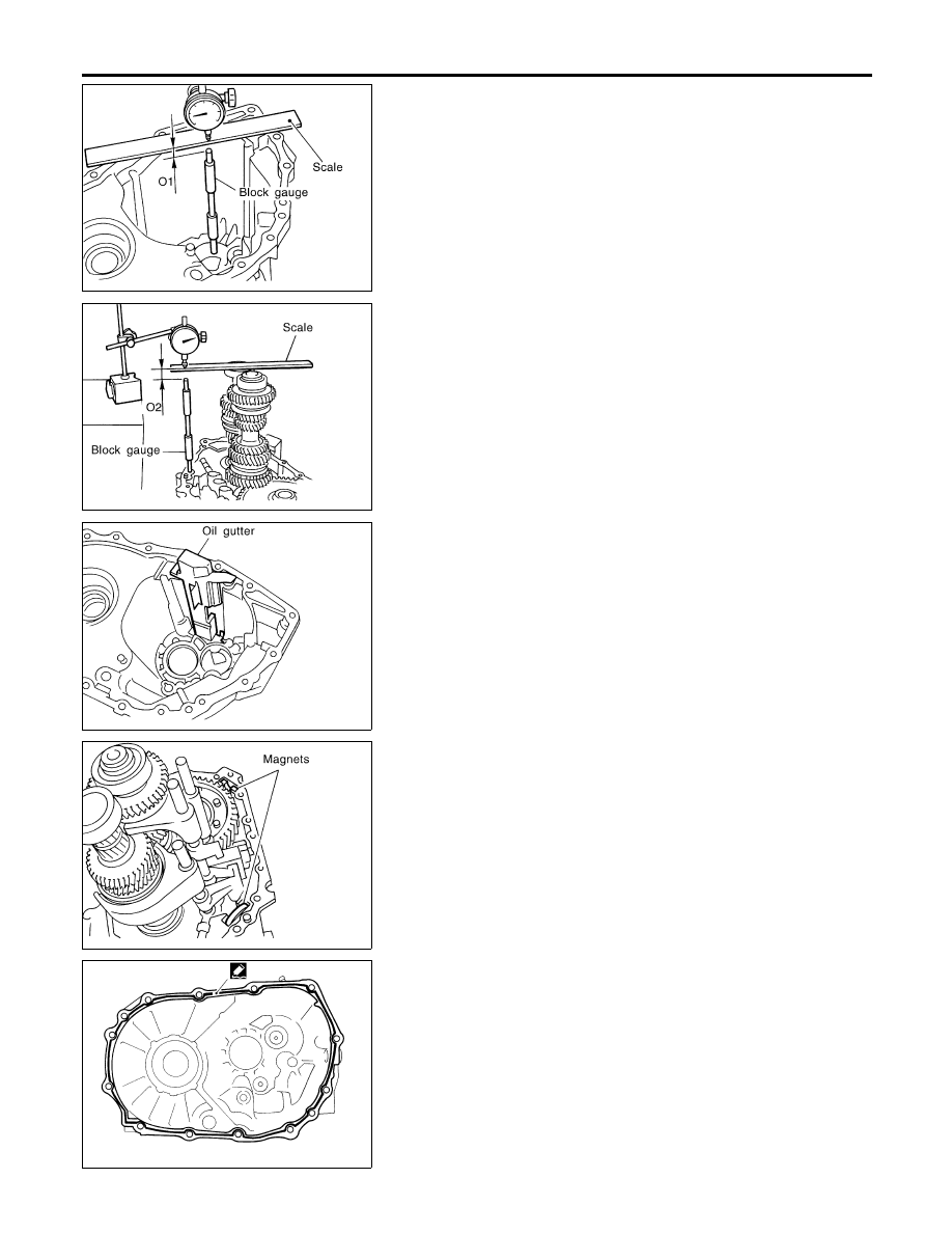
a.
Using block gauge, scale, and dial gauge, measure dimension
“O1” between transaxle case end face and mounting face of
adjusting shim.
SMT745D
b.
Using gauge block, scale, and dial gauge as shown in the
figure, measure dimension “O2” between clutch housing case
end face and end face of input shaft rear bearing.
7.
Install selected input shaft rear bearing adjusting shim onto
input shaft.
SMT650D
8.
Install oil gutter into transaxle case.
SMT755D
9.
Install two magnets.
SMT802D
10. Clean mating surfaces of clutch housing and transaxle case.
Check for cracks and damage. Then, apply Three Bond
TB1215, Loctite Part No. 51813 or equivalent.
ASSEMBLY
Transaxle Case (Cont’d)
MT-52
Нет комментариевНе стесняйтесь поделиться с нами вашим ценным мнением.
Текст