Infiniti G20 (P11). Manual — part 232
SEF998R
SEF853B
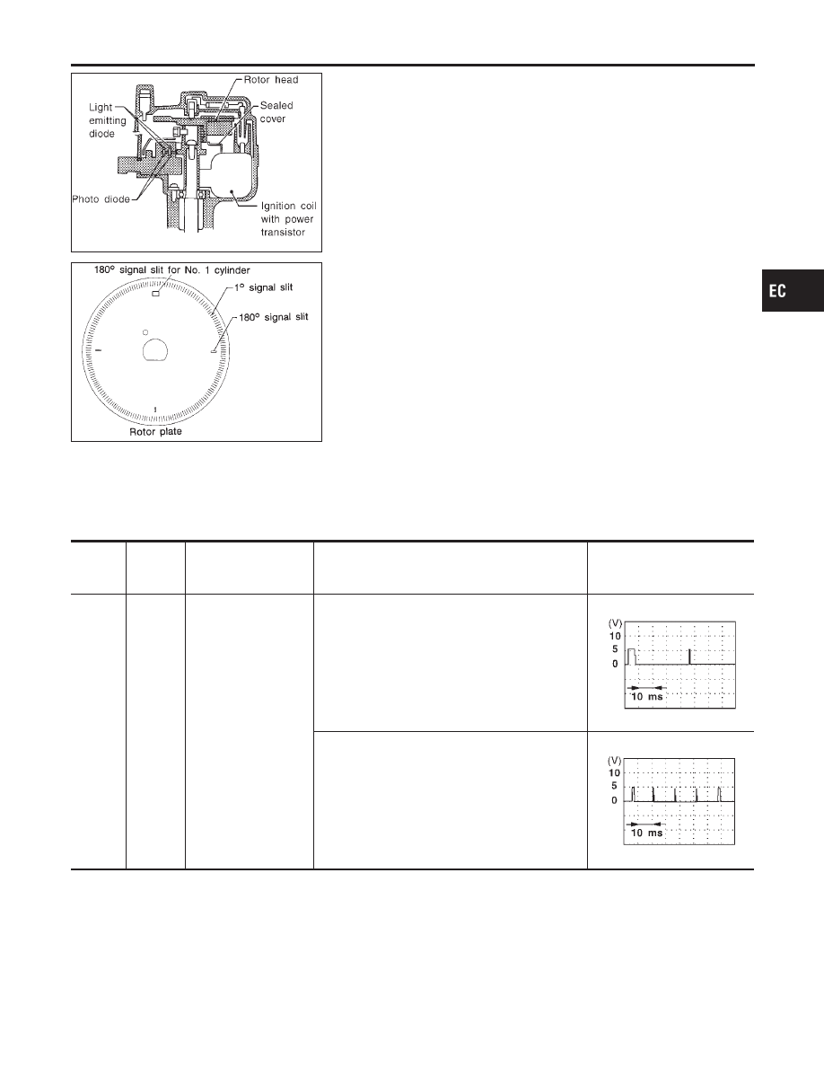
Component Description
NCEC0220
The camshaft position sensor is a basic component of the engine
control system. It monitors engine speed and piston position.
These input signals to the engine control system are used to con-
trol fuel injection, ignition timing and other functions.
The camshaft position sensor has a rotor plate and a wave-form-
ing circuit. The rotor plate has 360 slits for a 1° (POS) signal and
4 slits for a 180° (REF) signal. The wave-forming circuit consists
of Light Emitting Diodes (LED) and photo diodes.
The rotor plate is positioned between the LED and the photo diode.
The LED transmits light to the photo diode. As the rotor plate turns,
the slits cut the light to generate rough-shaped pulses. These
pulses are converted into on-off signals by the wave-forming circuit
and sent to the ECM.
The distributor is not repairable and must be replaced as an
assembly except distributor cap and rotor head.
ECM Terminals and Reference Value
NCEC0221
Specification data are reference values and are measured between each terminal and ground.
CAUTION:
Do not use ECM ground terminals when measuring input/output voltage. Doing so may result in dam-
age to the ECM’s transistor. Use a ground other than ECM terminals, such as the ground.
TERMI-
NAL
NO.
WIRE
COLOR
ITEM
CONDITION
DATA (DC Voltage)
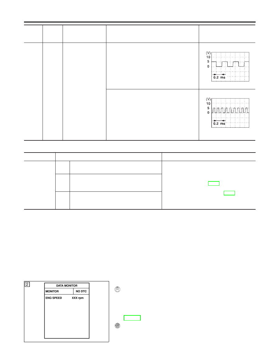
75
L
Camshaft position sen-
sor (Reference signal)
[Engine is running]
I
Warm-up condition
I
Idle speed
0.1 - 0.4V
SEF006W
[Engine is running]
I
Engine speed is 2,000 rpm
0.1 - 0.4V
SEF007W
GI
MA
EM
LC
FE
CL
MT
AT
AX
SU
BR
ST
RS
BT
HA
SC
EL
IDX
DTC P0340 CAMSHAFT POSITION SENSOR (CMPS)
Component Description
EC-339
TERMI-
NAL
NO.
WIRE
COLOR
ITEM
CONDITION
DATA (DC Voltage)
85
B/W
Camshaft position sen-
sor (Position signal)
[Engine is running]
I
Warm-up condition
I
Idle speed
Approximately 2.6V
SEF004W
[Engine is running]
I
Engine speed is 2,000 rpm
Approximately 2.5V
SEF005W
On Board Diagnosis Logic
NCEC0222
DTC No.
Malfunction is detected when ...
Check Items (Possible Cause)
P0340
A)
Either 1° or 180° signal is not sent to ECM for the
first few seconds during engine cranking.
I
Harness or connectors
(The camshaft position sensor circuit is open or
shorted.)
I
Camshaft position sensor
I
Starter motor (Refer to SC-10, “STARTING SYS-
TEM”.)
I
Starting system circuit (Refer to SC-10, “START-
ING SYSTEM”.)
I
Dead (Weak) battery
B)
Either 1° or 180° signal is not sent to ECM often
enough while the engine speed is higher than the
specified engine speed.
C)
The relation between 1° and 180° signal is not in
the normal range during the specified engine
speed.
DTC Confirmation Procedure
NCEC0223
Perform “Procedure for malfunction A” first. If DTC cannot be
confirmed, perform “Procedure for malfunction B and C”.
NOTE:
If “DTC Confirmation Procedure” has been previously conducted,
always turn ignition switch “OFF” and wait at least 10 seconds
before conducting the next test.
TESTING CONDITION:
Before performing the following procedure, confirm that bat-
tery voltage is more than 10.5V.
SEF058Y
PROCEDURE FOR MALFUNCTION A
NCEC0223S01
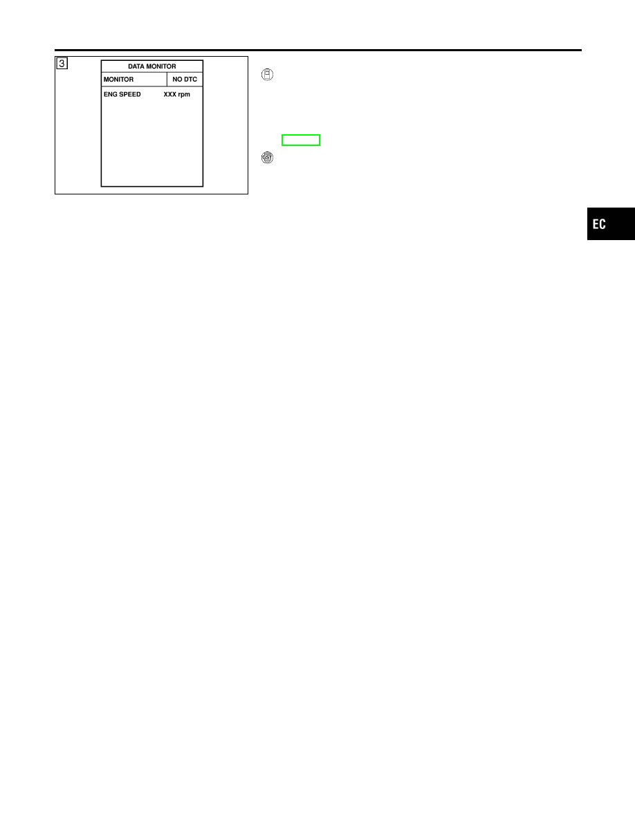
With CONSULT-II
1)
Turn ignition switch “ON”.
2)
Select “DATA MONITOR” mode with CONSULT-II.
3)
Crank engine for at least 2 seconds.
4)
If 1st trip DTC is detected, go to “Diagnostic Procedure”,
EC-343.
With GST
Follow the procedure “With CONSULT-II” above.
DTC P0340 CAMSHAFT POSITION SENSOR (CMPS)
ECM Terminals and Reference Value (Cont’d)
EC-340
SEF058Y
PROCEDURE FOR MALFUNCTION B AND C
NCEC0223S02
With CONSULT-II
1)
Turn ignition switch “ON”.
2)
Select “DATA MONITOR” mode with CONSULT-II.
3)
Start engine and run it for at least 2 seconds at idle speed.
4)
If 1st trip DTC is detected, go to “Diagnostic Procedure”,
EC-343.
With GST
Follow the procedure “With CONSULT-II” above.
GI
MA
EM
LC
FE
CL
MT
AT
AX
SU
BR
ST
RS
BT
HA
SC
EL
IDX
DTC P0340 CAMSHAFT POSITION SENSOR (CMPS)
DTC Confirmation Procedure (Cont’d)
EC-341
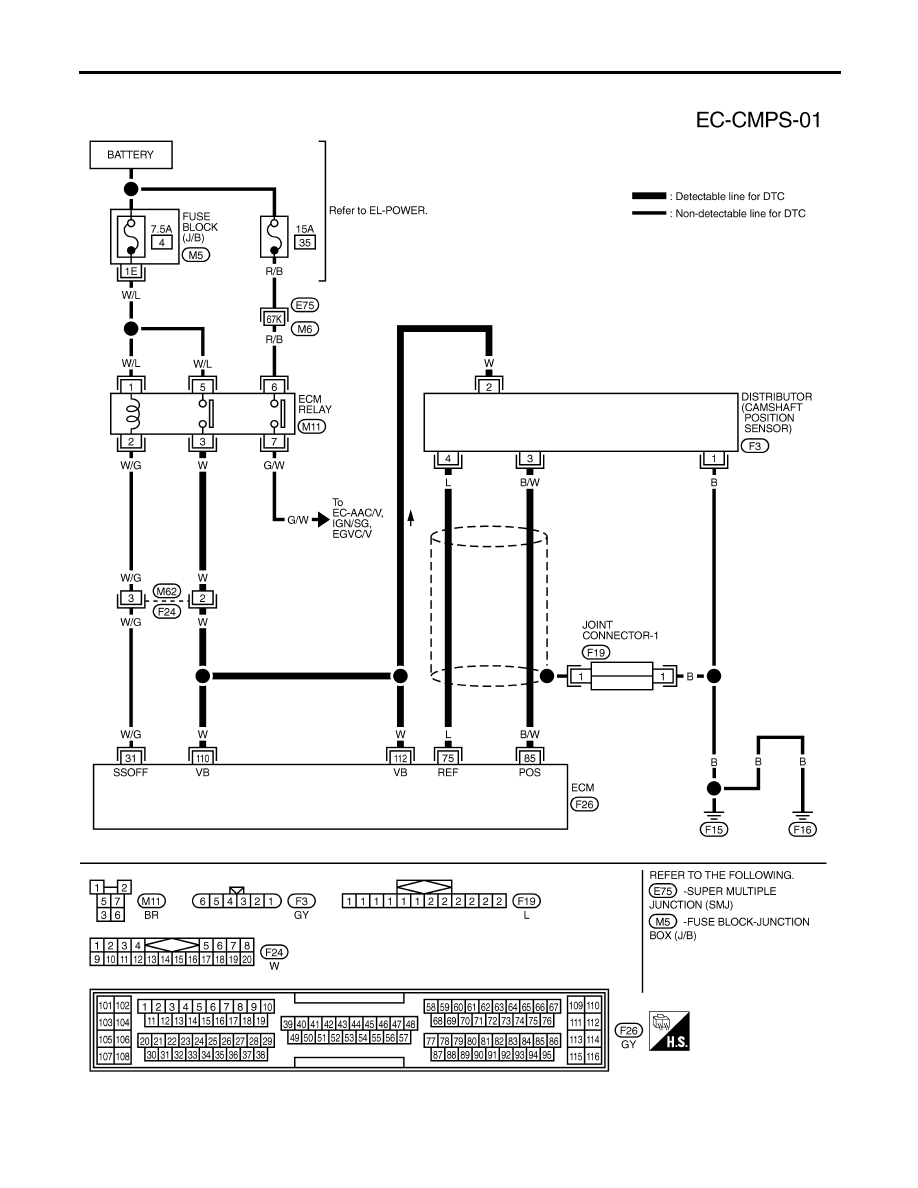
Wiring Diagram
NCEC0224
TEC828
DTC P0340 CAMSHAFT POSITION SENSOR (CMPS)
Wiring Diagram
EC-342
Нет комментариевНе стесняйтесь поделиться с нами вашим ценным мнением.
Текст