Infiniti G20 (P11). Manual — part 388
SEM927C
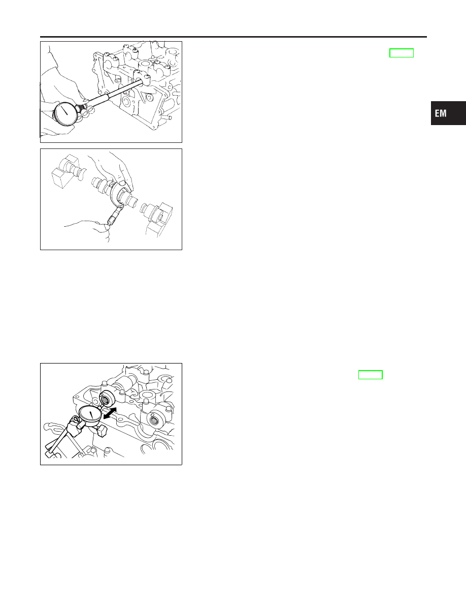
CAMSHAFT JOURNAL CLEARANCE
1.
Install camshaft bracket and tighten bolts. Refer to EM-23.
2.
Measure inner diameter of camshaft bearing.
Standard inner diameter:
28.000 - 28.021 mm (1.1024 - 1.1032 in)
SEM012A
3.
Measure outer diameter of camshaft journal.
Standard outer diameter:
27.935 - 27.955 mm (1.0998 - 1.1006 in)
4.
Calculate camshaft journal clearance.
Camshaft journal clearance = standard inner diameter
− standard outer diameter:
Standard
0.030 - 0.071 mm (0.0012 - 0.0028 in)
Limit
0.15 mm (0.0059 in)
5.
If clearance exceeds the limit, replace camshaft and remea-
sure camshaft journal clearance.
I
If clearance still exceeds the limit after replacing camshaft,
replace cylinder head.
SEM062G
CAMSHAFT END PLAY
NCEM0019S06
1.
Install camshaft in cylinder head. Refer to EM-23.
2.
Measure camshaft end play.
Camshaft end play:
Standard
0.055 - 0.139 mm (0.0022 - 0.0055 in)
Limit
0.20 mm (0.0079 in)
3.
If end play exceeds the limit, replace camshaft and remeasure
camshaft end play.
I
If end play still exceeds the limit after replacing camshaft,
replace cylinder head.
GI
MA
LC
EC
FE
CL
MT
AT
AX
SU
BR
ST
RS
BT
HA
SC
EL
IDX
CYLINDER HEAD
Inspection (Cont’d)
EM-37
SEM929C
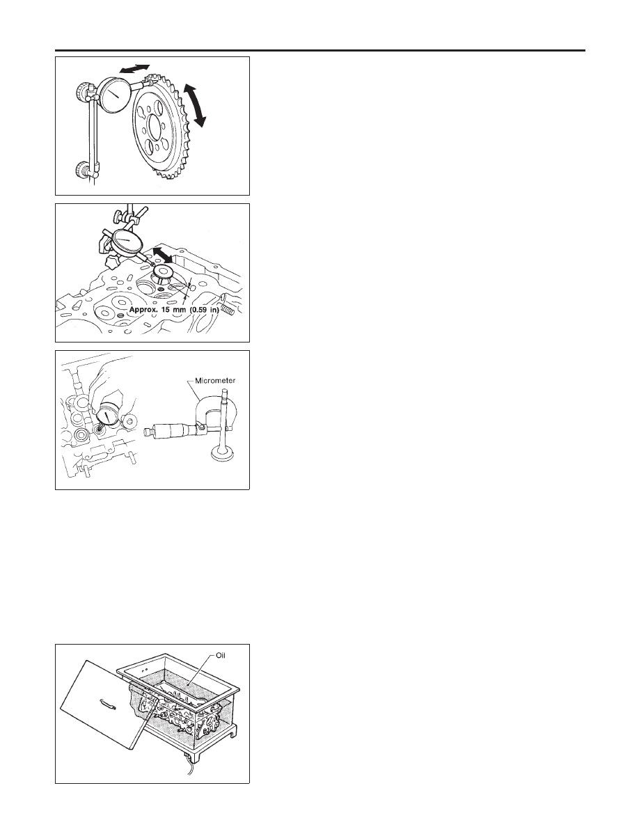
CAMSHAFT SPROCKET RUNOUT
NCEM0019S07
1.
Install sprocket on camshaft.
2.
Measure camshaft sprocket runout.
Runout (Total indicator reading):
Limit 0.25 mm (0.0098 in)
3.
If it exceeds the limit, replace camshaft sprocket.
SEM003D
VALVE GUIDE CLEARANCE
NCEM0019S08
1.
Measure valve deflection as shown in illustration. (Valve and
valve guide mostly wear in this direction.)
Valve deflection limit (Dial gauge reading):
Intake & Exhaust
0.2 mm (0.008 in)
SEM938C
2.
If it exceeds the limit, check valve to valve guide clearance.
a.
Measure valve stem diameter and valve guide inner diameter.
b.
Calculate valve to valve guide clearance.
Valve to valve guide clearance = valve guide inner
diameter − valve stem diameter:
Standard
Intake 0.020 - 0.053 mm (0.0008 - 0.0021 in)
Exhaust 0.040 - 0.073 mm (0.0016 - 0.0029 in)
Limit
Intake 0.08 mm (0.0031 in)
Exhaust 0.1 mm (0.004 in)
c.
If it exceeds the limit, replace valve and remeasure clearance.
I
If clearance still exceeds the limit after replacing valve, replace
valve guide.
SEM008A
VALVE GUIDE REPLACEMENT
NCEM0019S09
1.
To remove valve guide, heat cylinder head to 110 to 130°C
(230 to 266°F).
CYLINDER HEAD
Inspection (Cont’d)
EM-38
SEM931C
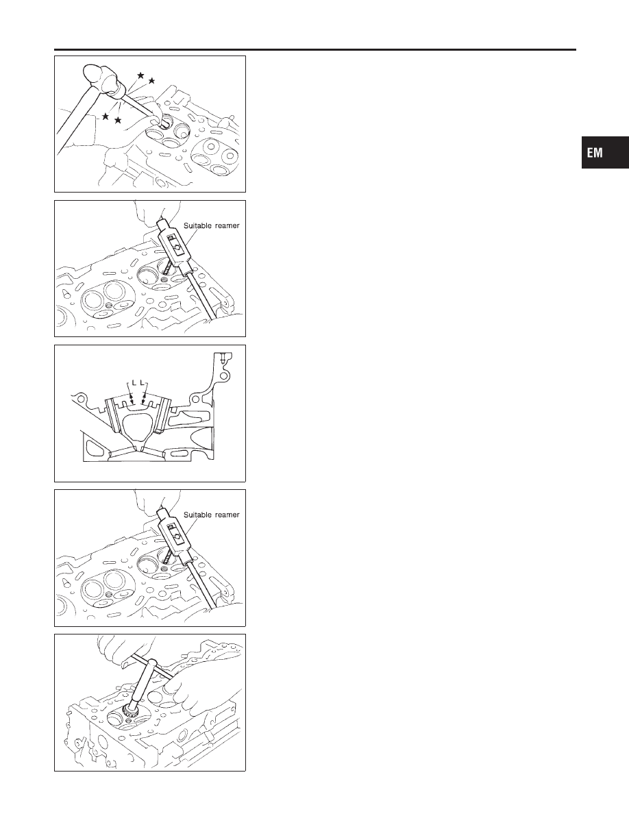
2.
Drive out valve guide with a press (under a 20 kN [2 ton, 2.2
US ton, 2.0 Imp ton] pressure) or hammer and suitable tool.
SEM932C
3.
Ream cylinder head valve guide hole.
Valve guide hole diameter
(for service parts):
Intake & Exhaust
10.175 - 10.196 mm (0.4006 - 0.4014 in)
SEM083D
4.
Heat cylinder head to 110 to 130°C (230 to 266°F) and press
service valve guide into cylinder head.
Projection “L”:
14.0 - 14.2 mm (0.551 - 0.559 in)
SEM932C
5.
Ream valve guide.
Finished size:
Intake & Exhaust
6.000 - 6.018 mm (0.2362 - 0.2369 in)
SEM934C
VALVE SEATS
NCEM0019S10
Check valve seats for pitting at contact surface. Resurface or
replace if excessively worn.
I
Before repairing valve seats, check valve and valve guide
for wear. If they are worn, replace them. Then correct valve
seat.
I
Use both hands to cut uniformly.
GI
MA
LC
EC
FE
CL
MT
AT
AX
SU
BR
ST
RS
BT
HA
SC
EL
IDX
CYLINDER HEAD
Inspection (Cont’d)
EM-39
SEM795A
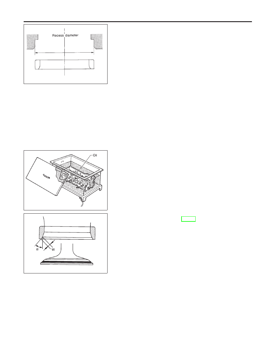
REPLACING VALVE SEAT FOR SERVICE PARTS
NCEM0019S11
1.
Bore out old seat until it collapses. Set machine depth stop so
that boring cannot contact bottom face of seat recess in cylin-
der head.
2.
Ream cylinder head recess.
Reaming bore for service valve seat
Oversize [0.5 mm (0.020 in)]:
Intake 35.500 - 35.516 mm (1.3976 - 1.3983 in)
Exhaust 31.500 - 31.516 mm (1.2402 - 1.2408 in)
Use the valve guide center for reaming to ensure valve seat
will have the correct fit.
SEM008A
3.
Heat cylinder head to 110 to 130°C (230 to 266°F).
4.
Press fit valve seat until it seats on the bottom.
SEM892B
5.
Cut or grind valve seat to the specified dimensions using a
suitable tool. Refer to SDS, EM-72.
6.
After cutting, lap valve seat with abrasive compound.
7.
Check valve seating condition.
Seat face angle “
α
”:
44°53
′
- 45°07
′
Contacting width “W”:
Intake
1.05 - 1.35 mm (0.0413 - 0.0531 in)
Exhaust
1.25 - 1.55 mm (0.0492 - 0.0610 in)
CYLINDER HEAD
Inspection (Cont’d)
EM-40
Нет комментариевНе стесняйтесь поделиться с нами вашим ценным мнением.
Текст