Infiniti G20 (P11). Manual — part 517
DIAGNOSTIC RESULT ITEM CHART
NCSC0018S01
Diagnostic item
Service procedure
GOOD BATTERY
Battery is OK, go to “Trouble Diagnoses”, “STARTING SYSTEM”. Refer to SC-13.
REPLACE BATTERY
Replace battery.
Before replacing battery, clean the battery cable clamps and battery posts. Perform battery
test again with Battery/Starting/Charging system tester. If second test result is “Replace
Battery”, then do so. Perform battery test again to confirm repair.
BAD CELL-REPLACE
Replace the battery. Perform battery test again with Battery/Starting/Charging system
tester to confirm repair.
GOOD-RECHARGE
Perform the slow battery charging procedure. (Initial rate of charge is 10A for 12 hours.)
Perform battery test again with Battery/Starting/Charging system tester.
CHARGE & RETEST
Perform the slow battery charging. (Initial rate of charge is 10A for 12 hours.)
Perform battery test again with Battery/Starting/Charging system tester to confirm repair.
NOTE:
If the tester asks the user “BEFORE CHARGE/AFTER CHARGE”, select “AFTER
CHARGE”.
GI
MA
EM
LC
EC
FE
CL
MT
AT
AX
SU
BR
ST
RS
BT
HA
EL
IDX
BATTERY
Trouble Diagnoses with Battery/Starting/Charging System Tester (Cont’d)
SC-9
System Description
NCSC0004
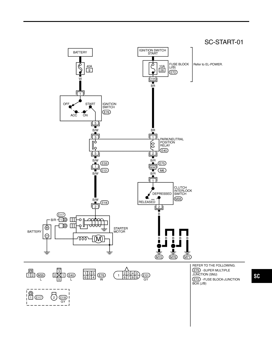
M/T MODELS
NCSC0004S01
Power is supplied at all times
I
to ignition switch terminal 1
I
through 40A fusible link (letter g, located in the fuse and fusible link box).
With the ignition switch in the START position, power is supplied through 10A fuse [No. 26, located in the fuse
block (J/B)]
I
to park/neutral position relay terminal 1.
Also, with the ignition switch in the START position, power is supplied
I
from ignition switch terminal 5
I
to park/neutral position relay terminal 3.
When the clutch pedal is depressed, ground is supplied
I
to park/neutral position relay terminal 2 through the clutch interlock switch
I
from body grounds M15, M71 and M76.
Then park/neutral position relay is energized and power is supplied
I
from park/neutral position relay terminal 5
I
to starter motor harness connector terminal 2.
The starter motor plunger closes and provides a closed circuit between the battery and starter motor. The
starter motor is grounded to the engine block. With power and ground supplied, cranking occurs and the engine
starts.
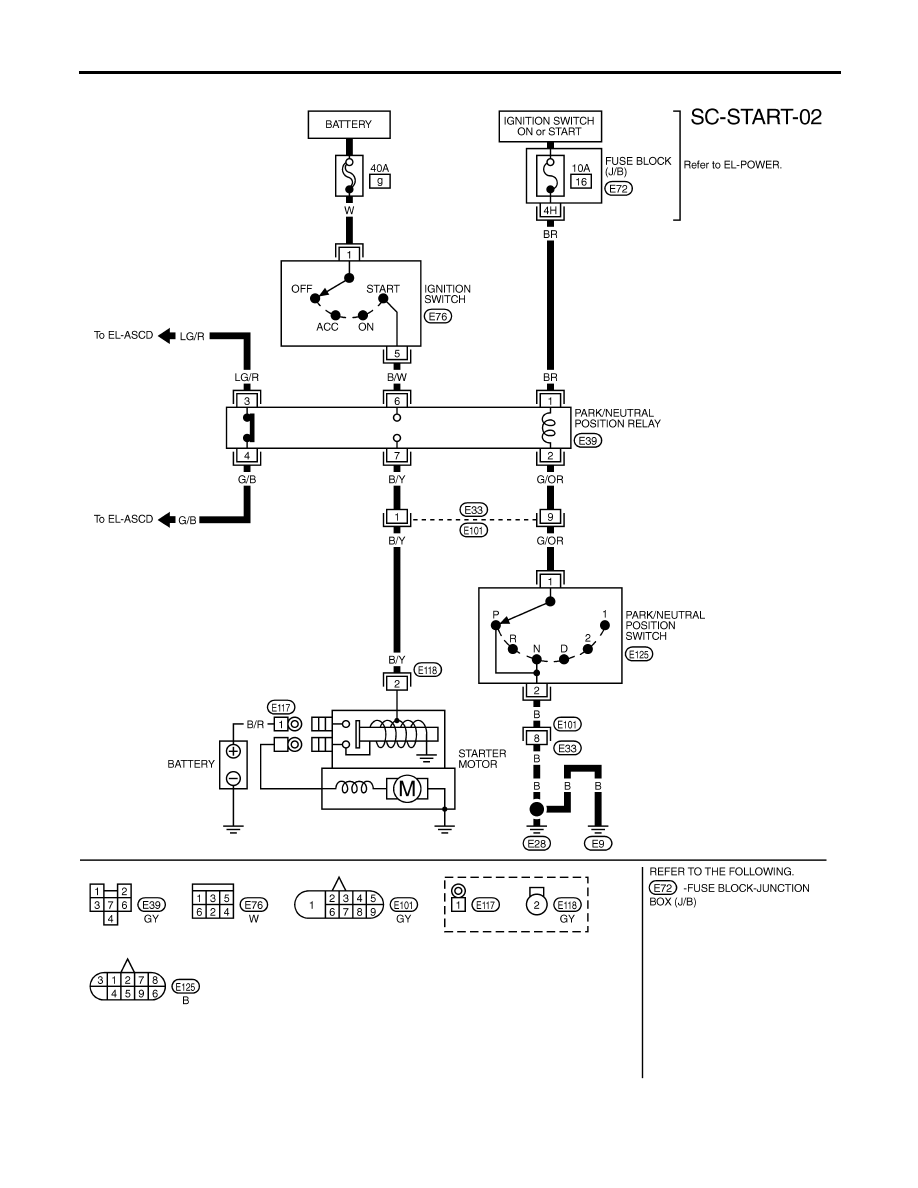
A/T MODELS
NCSC0004S02
Power is supplied at all times
I
to ignition switch terminal 1
I
through 40A fusible link (letter g, located in the fuse and fusible link box).
With the ignition switch in the ON or START position, power is supplied through 10A fuse [No. 16, located in
the fuse block (J/B)]
I
to park/neutral position relay terminal 1.
Also, with the ignition switch in the START position, power is supplied
I
from ignition switch terminal 5
I
to park/neutral position relay terminal 6.
With the selector lever in the P or N position, ground is supplied
I
to park/neutral position relay terminal 2 through the park/neutral position switch
I
from body grounds, E28 and E9.
Then park/neutral position relay is energized and power is supplied
I
from park/neutral position relay terminal 7
I
to starter motor harness connector terminal 2.
The starter motor plunger closes and provides a closed circuit between the battery and starter motor. The
starter motor is grounded to the engine block. With power and ground supplied, cranking occurs and the engine
starts.
STARTING SYSTEM
System Description
SC-10
Wiring Diagram — START —
NCSC0005
M/T MODELS
NCSC0005S01
TSC004
GI
MA
EM
LC
EC
FE
CL
MT
AT
AX
SU
BR
ST
RS
BT
HA
EL
IDX
STARTING SYSTEM
Wiring Diagram — START —
SC-11
A/T MODELS
NCSC0005S02
TSC005
STARTING SYSTEM
Wiring Diagram — START — (Cont’d)
SC-12
Нет комментариевНе стесняйтесь поделиться с нами вашим ценным мнением.
Текст