Infiniti G20 (P11). Manual — part 246
9
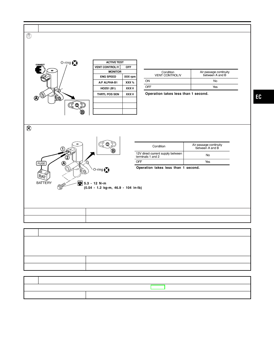
CHECK EVAP CANISTER VENT CONTROL VALVE-II
With CONSULT-II
1. Reconnect harness connectors disconnected.
2. Turn ignition switch “ON”.
3. Perform “VENT CONTROL/V” in “ACTIVE TEST” mode.
4. Check air passage continuity and operation delay time.
SEF803Y
Without CONSULT-II
Check air passage continuity and operation delay time under the following conditions.
SEF339X
Make sure new O-ring is installed properly.
OK or NG
OK
©
GO TO 11.
NG
©
GO TO 10.
10
CHECK EVAP CANISTER VENT CONTROL VALVE-III
1. Clean the air passage (Portion A to B) of EVAP canister vent control valve using an air blower.
2. Perform Test No. 9 again.
OK or NG
OK
©
GO TO 11.
NG
©
Replace EVAP canister vent control valve.
11
CHECK INTERMITTENT INCIDENT
Refer to “TROUBLE DIAGNOSIS FOR INTERMITTENT INCIDENT”, EC-146.
©
INSPECTION END
GI
MA
EM
LC
FE
CL
MT
AT
AX
SU
BR
ST
RS
BT
HA
SC
EL
IDX
DTC P0446 EVAPORATIVE EMISSION (EVAP) CANISTER VENT CONTROL
VALVE (CIRCUIT)
Diagnostic Procedure (Cont’d)
EC-395
SEF053V
SEF954S
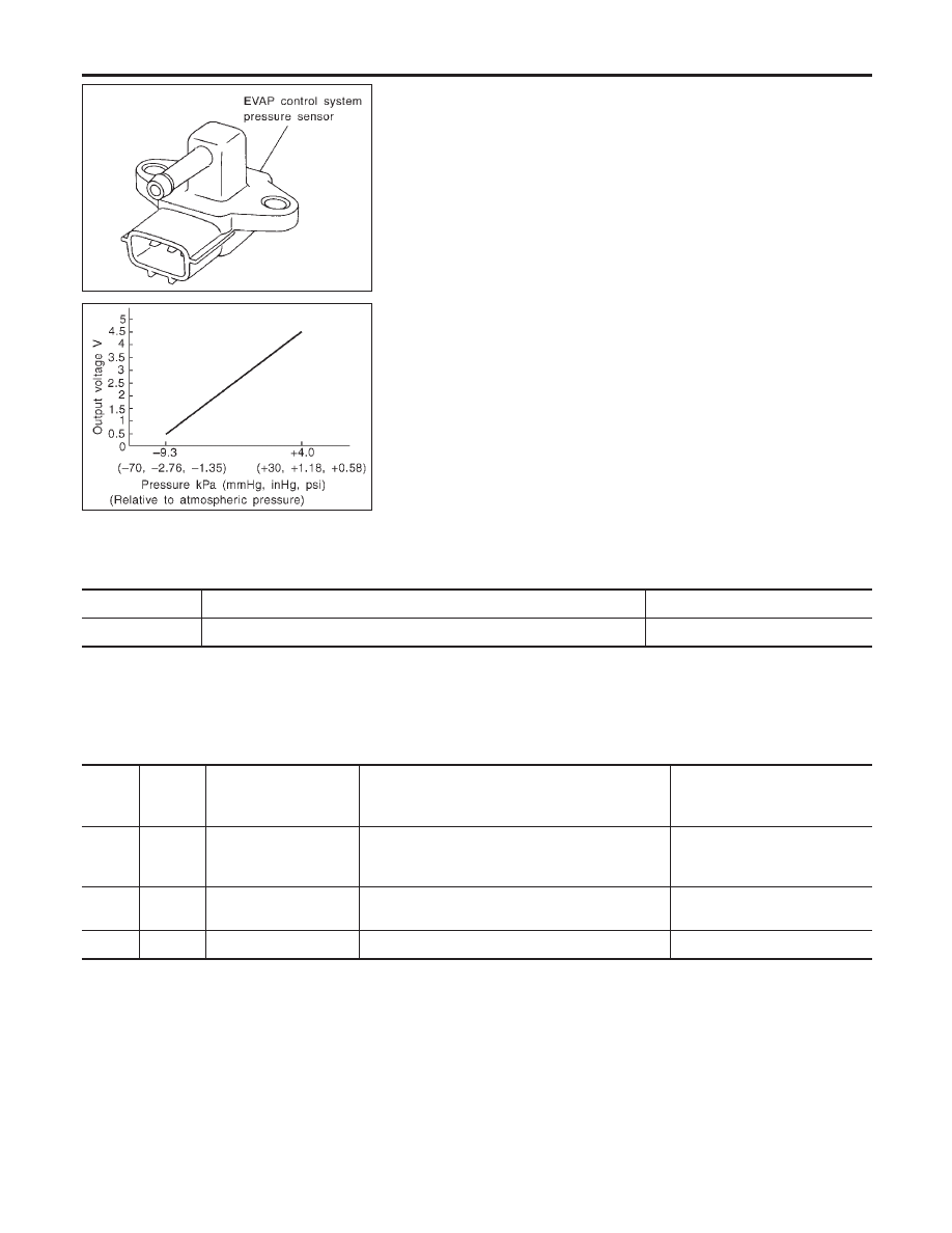
Component Description
NCEC0545
The EVAP control system pressure sensor detects pressure in the
purge line. The sensor output voltage to the ECM increases as
pressure increases. The EVAP control system pressure sensor is
not used to control the engine system. It is used only for on board
diagnosis.
CONSULT-II Reference Value in Data Monitor
Mode
NCEC0546
Specification data are reference values.
MONITOR ITEM
CONDITION
SPECIFICATION
EVAP SYS PRES
I
Ignition switch: ON
Approx. 3.4V
ECM Terminals and Reference Value
NCEC0648
Specification data are reference values and are measured between each terminal and ground.
CAUTION:
Do not use ECM ground terminals when measuring input/output voltage. Doing so may result in dam-
age to the ECM’s transistor. Use a ground other than ECM terminals, such as the ground.
TER-
MINAL
NO.
WIRE
COLOR
ITEM
CONDITION
DATA (DC Voltage)
58
B
Sensor’s ground
[Engine is running]
I
Warm-up condition
I
Idle speed
Approximately 0V
84
W
EVAP control system
pressure sensor
[Ignition switch “ON”]
Approximately 3.4V
111
P/L
Sensor’s power supply
[Ignition switch “ON”]
Approximately 5V
DTC P0450 EVAPORATIVE EMISSION (EVAP) CONTROL SYSTEM PRESSURE
SENSOR
Component Description
EC-396
On Board Diagnosis Logic
NCEC0547
Malfunction is detected when an improper voltage signal from
EVAP control system pressure sensor is sent to ECM.
Possible Cause
NCEC0548
I
Harness or connectors
(The EVAP control system pressure sensor circuit is open or
shorted.)
I
Rubber hose to EVAP control system pressure sensor is
clogged, vent, kinked, disconnected or improper connection.
I
EVAP control system pressure sensor
I
EVAP canister vent control valve
I
EVAP canister purge volume control solenoid valve
I
EVAP canister
I
Rubber hose from EVAP canister vent control valve to water
separator
DTC Confirmation Procedure
NCEC0549
NOTE:
If “DTC Confirmation Procedure” has been previously conducted,
always turn ignition switch “OFF” and wait at least 10 seconds
before conducting the next test.
TESTING CONDITION:
Always perform test at a temperature of 5°C (41°F) or more.
SEF194Y
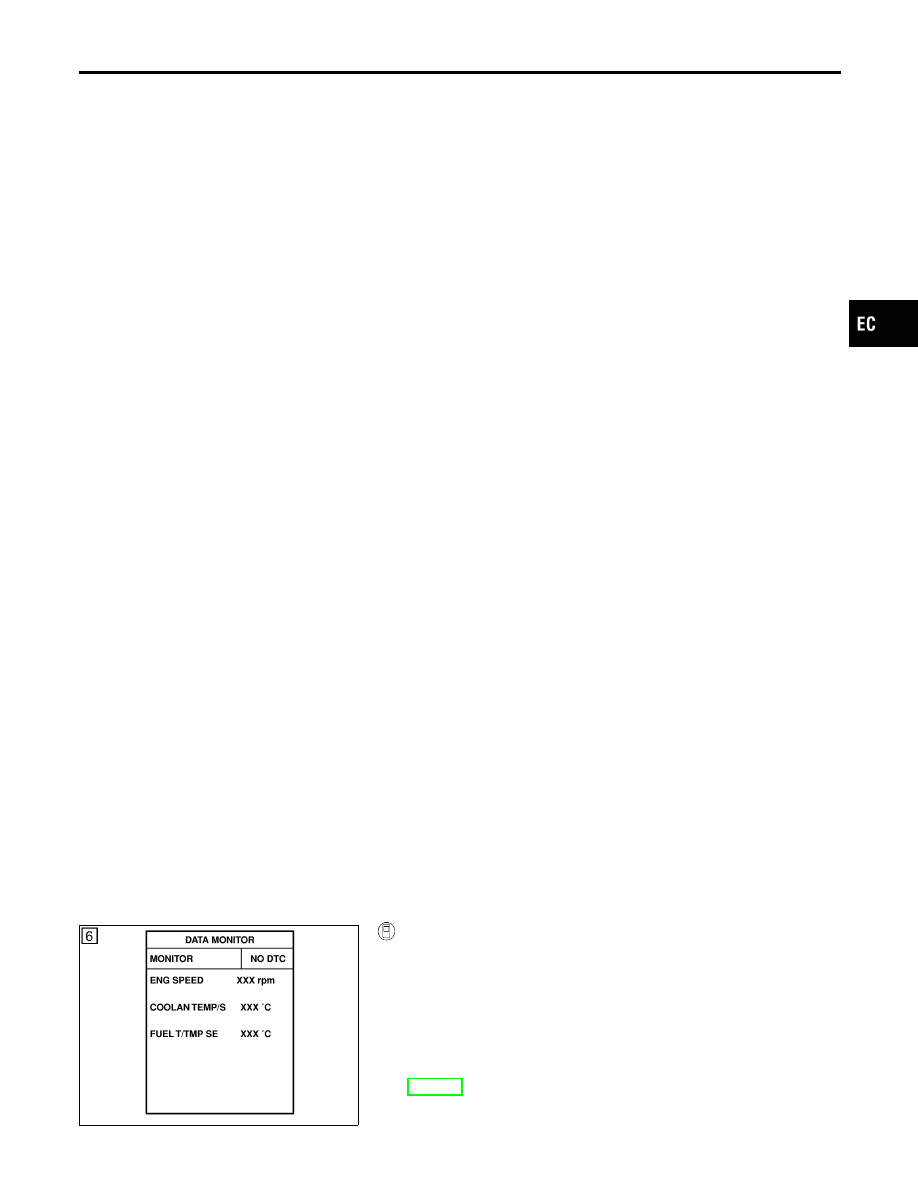
WITH CONSULT-II
NCEC0549S01
1)
Start engine and warm it up to normal operating temperature.
2)
Turn ignition switch “OFF” and wait at least 10 seconds.
3)
Turn ignition switch “ON”.
4)
Select “DATA MONITOR” mode with CONSULT-II.
5)
Make sure that “FUEL T/TEMP SE” is more than 0°C (32°F).
6)
Start engine and wait at least 20 seconds.
7)
If 1st trip DTC is detected, go to “Diagnostic Procedure”,
EC-400.
GI
MA
EM
LC
FE
CL
MT
AT
AX
SU
BR
ST
RS
BT
HA
SC
EL
IDX
DTC P0450 EVAPORATIVE EMISSION (EVAP) CONTROL SYSTEM PRESSURE
SENSOR
On Board Diagnosis Logic
EC-397
SEF938X
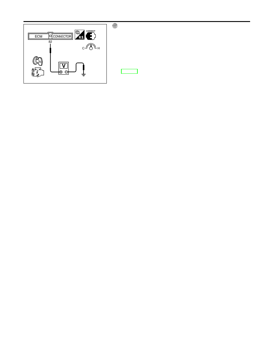
WITH GST
NCEC0549S02
1)
Start engine and warm it up to normal operating temperature.
2)
Check that voltage between ECM terminal 82 (Fuel tank tem-
perature sensor signal) and ground is less than 4.2V.
3)
Turn ignition switch “OFF” and wait at least 10 seconds.
4)
Start engine and wait at least 20 seconds.
5)
Select “MODE 7” with GST.
6)
If 1st trip DTC is detected, go to “Diagnostic Procedure”,
EC-400.
DTC P0450 EVAPORATIVE EMISSION (EVAP) CONTROL SYSTEM PRESSURE
SENSOR
DTC Confirmation Procedure (Cont’d)
EC-398
Нет комментариевНе стесняйтесь поделиться с нами вашим ценным мнением.
Текст