Infiniti G20 (P11). Manual — part 325
TEL843B
GI
MA
EM
LC
EC
FE
CL
MT
AT
AX
SU
BR
ST
RS
BT
HA
SC
IDX
ILLUMINATION
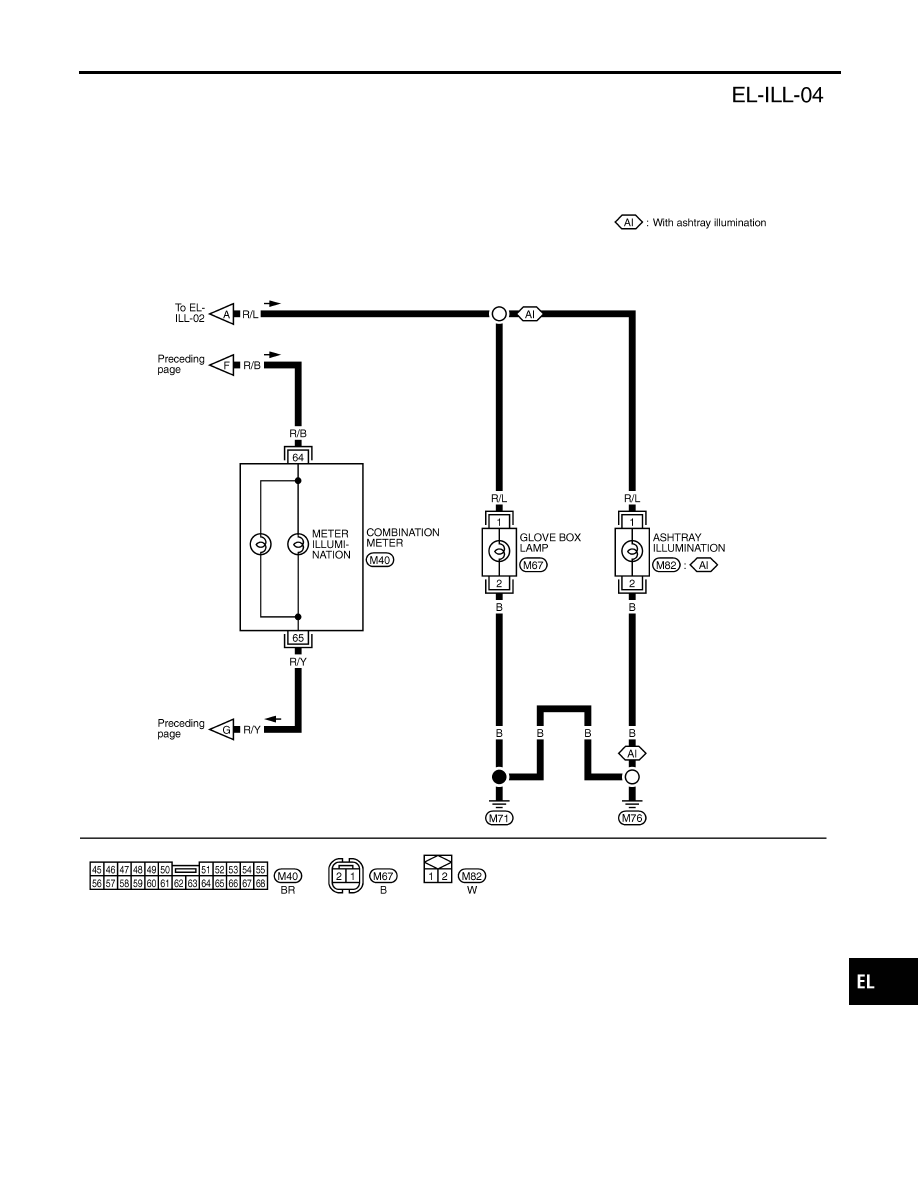
Wiring Diagram — ILL — (Cont’d)
EL-77
System Description
NCEL0162
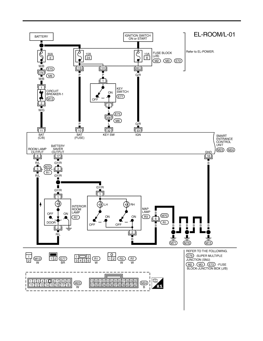
POWER SUPPLY AND GROUND
NCEL0162S01
Power is supplied at all times:
I
through 30A fusible link (Letter d, located in the fuse and fusible link box)
I
to circuit breaker-1 terminal 1
I
through circuit breaker-1 terminal 2
I
to smart entrance control unit terminal 11.
Power is supplied at all times:
I
through 10A fuse [No. 24, located in the fuse block (J/B)]
I
to key switch terminal 1 and
I
to smart entrance control unit terminal 10.
When the key is removed from ignition key cylinder, power is interrupted:
I
through terminal key switch 2
I
to smart entrance control unit terminal 32.
With the ignition key switch in the ON or START position, power is supplied:
I
through 10A fuse [No. 8, located in the fuse block (J/B)]
I
to smart entrance control unit terminal 33.
Ground is supplied:
I
to smart entrance control unit terminal 16
I
through body grounds terminal M15, M71 and M76.
When the front driver side door is opened, ground is supplied:
I
through body grounds B7 and B24
I
to front door switch (driver side) terminal 3
I
from front door switch (driver side) terminal 2
I
to smart entrance control unit terminal 29.
When the front passenger side door is opened, ground is supplied:
I
through case ground of front door switch (passenger side)
I
from front door switch (passenger side) terminal 1
I
to smart entrance control unit terminal 40.
When any other door (except front passenger side) is opened ground is supplied to smart entrance control
unit terminal 28 in the same manner as the front door switch (front passenger side).
When the driver side door is unlocked, the smart entrance control unit receives a ground signal:
I
through body grounds terminal M15, M71 and M76
I
to front door lock actuator (driver side) (unlock sensor) terminal 2
I
from front door lock actuator (driver side) (unlock sensor) terminal 4
I
to smart entrance control unit terminal 36.
When a signal, or combination of signals is received by the smart entrance control unit, ground is supplied:
I
through smart entrance control unit terminal 8
I
to interior room lamp terminal 2.
With power and ground supplied, the interior room lamp illuminates.
SWITCH OPERATION
NCEL0162S03
When the room lamp switch is ON, ground is supplied:
I
through case grounds of interior room lamp
I
from interior room lamp terminal 1
I
to smart entrance control unit terminal 17.
When the map lamp (LH and/or RH) is ON, ground is supplied:
I
through body grounds M15, M71 and M76
I
to map lamp terminal 2
I
from map lamp terminal 1
I
to smart entrance control unit terminal 17.
With power and ground supplied, the room lamp turns ON.
INTERIOR ROOM LAMP
System Description
EL-78
INTERIOR ROOM LAMP TIMER OPERATION
NCEL0162S04
When interior lamp switch is in the “DOOR” position, the smart entrance control unit keeps the interior lamp
illuminated for about 30 seconds when:
I
unlock signal is supplied from driver’s door unlock sensor while all doors are closed and key is removed
from ignition key cylinder
I
key is removed from ignition key cylinder while all doors are closed
I
driver’s door is opened and then closed while key is removed from the iginition key cylinder. (However, if
the driver’s door is closed with the key insered in the ignition key cylinder after the driver’s door is opened
with the key removed, the timer is operated.)
When the interior lamp switch is in the “DOOR” position and the unlock signal is supplied from the multi-re-
mote controller while the driver’s door is locked and all doors are closed (even if key is inserted), the smart
entrance control unit keeps the interior lamp illuminated for about 30 senconds.
The timer is canceled when:
I
driver’s door is locked,
I
driver’s door is opened, or
I
ignition switch is turned ON.
ON-OFF CONTROL
NCEL0162S05
When the driver side door, front passenger door, rear LH or RH door is opened, the interior room lamp turns
on while the interior room lamp switch is in the “DOOR” position.
BATTERY SAVER
NCEL0162S06
The lamp turns off automatically when interior lamp, and/or map lamp is illuminated with the ignition key is in
OFF position, if the lamp remains lit by the door switch open signal or if the lamp switch is in ON position for
more than 10 minutes.
After lamps turn off by the battery saver system, the lamps illuminate again when:
I
driver’s door is locked or unlocked,
I
door is opened or closed,
I
key is inserted in ignition key cylinder.
GI
MA
EM
LC
EC
FE
CL
MT
AT
AX
SU
BR
ST
RS
BT
HA
SC
IDX
INTERIOR ROOM LAMP
System Description (Cont’d)
EL-79
Wiring Diagram — ROOM/L —
NCEL0163
TEL844B
INTERIOR ROOM LAMP
Wiring Diagram — ROOM/L —
EL-80
Нет комментариевНе стесняйтесь поделиться с нами вашим ценным мнением.
Текст