Infiniti G20 (P11). Manual — part 160
SEF718B
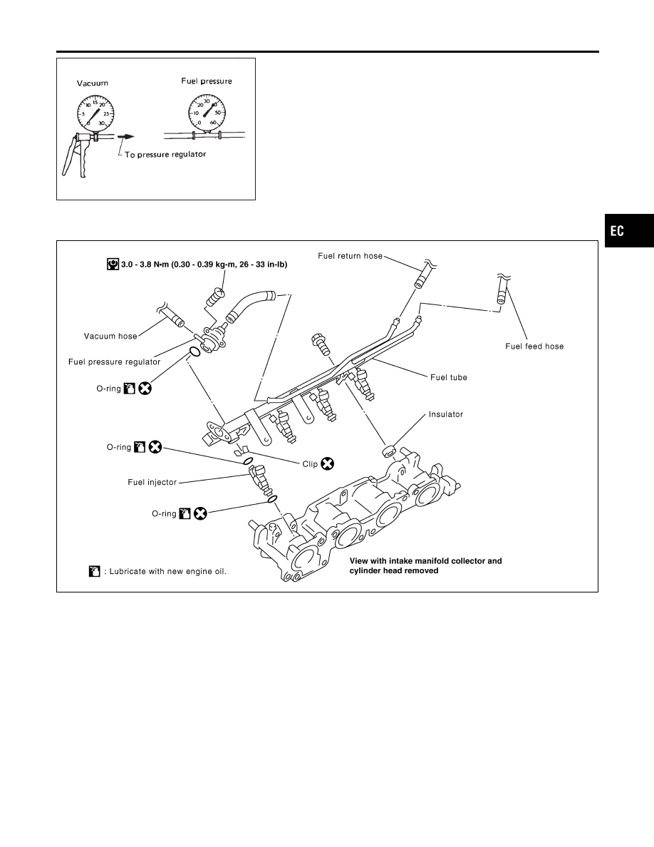
Fuel Pressure Regulator Check
NCEC0026
1.
Stop engine and disconnect fuel pressure regulator vacuum
hose from intake manifold collector.
2.
Plug intake manifold collector with a rubber cap.
3.
Connect variable vacuum source to fuel pressure regulator.
4.
Start engine and read indication of fuel pressure gauge as
vacuum is changed.
Fuel pressure should decrease as vacuum increases. If results
are unsatisfactory, replace fuel pressure regulator.
Injector
REMOVAL AND INSTALLATION
NCEC0027
SEF910Z
1.
Release fuel pressure to zero.
2.
Remove accelerator wire bracket.
3.
Remove EVAP canister purge volume control solenoid valve
and the bracket.
4.
Remove ventilation hose.
5.
Disconnect injector harness connectors.
6.
Disconnect fuel pressure regulator vacuum hose from intake
manifold collector.
7.
Disconnect fuel hoses from fuel tube assembly.
8.
Remove injectors with fuel tube assembly.
GI
MA
EM
LC
FE
CL
MT
AT
AX
SU
BR
ST
RS
BT
HA
SC
EL
IDX
BASIC SERVICE PROCEDURE
Fuel Pressure Regulator Check
EC-51
SEF703X
9.
Expand and remove clips securing fuel injectors.
10. Extract fuel injectors straight from fuel tubes.
I
Be careful not to damage injector nozzles during removal.
I
Do not bump or drop fuel injectors.
11. Carefully install O-rings, including the one used with the pres-
sure regulator.
I
Lubricate O-rings with a smear of engine oil.
I
Be careful not to damage O-rings with service tools or
finger nails or clips. Do not expand or twist O-rings.
I
Discard old clips; replace with new ones.
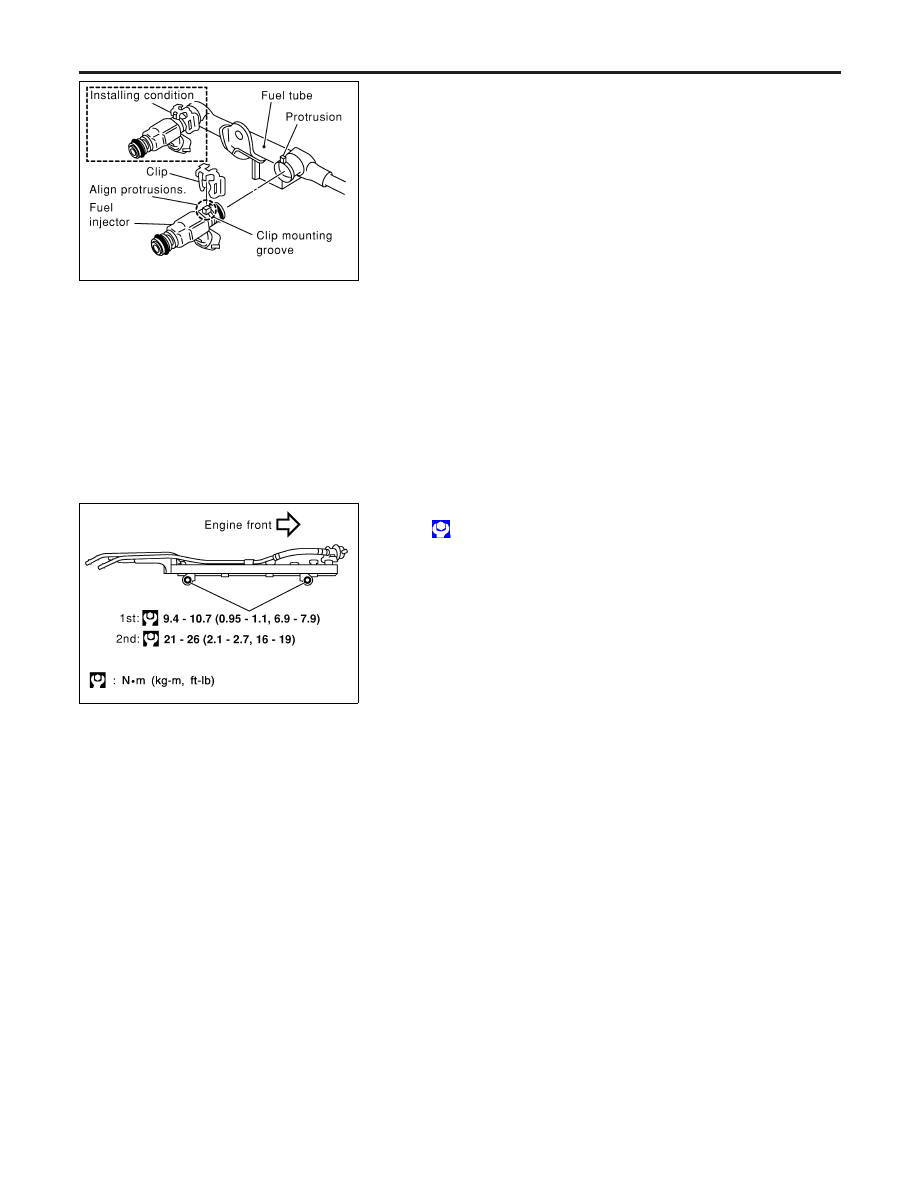
12. Position clips in grooves on fuel injectors.
I
Make sure that protrusions of fuel injectors are aligned
with cutouts of clips after installation.
13. Align protrusions of fuel tubes with those of fuel injectors.
14. After properly inserting fuel injectors, check to make sure that
fuel tube protrusions are engaged with those of fuel injectors,
and that flanges of fuel tubes are engaged with clips.
SEF828X
15. Tighten fuel tube assembly mounting nuts in two stages.
: Tightening torque N·m (kg-m, ft-lb)
1st stage:
9.4 - 10.7 (0.95 - 1.1, 6.9 - 7.9)
2nd stage:
21 - 26 (2.1 - 2.7, 16 - 19)
16. Install all removed parts in the reverse order of removal.
CAUTION:
After properly connecting fuel tube assembly to injector and
fuel hose, check connection for fuel leakage.
BASIC SERVICE PROCEDURE
Injector (Cont’d)
EC-52
Idle Speed/Ignition Timing/Idle Mixture Ratio
Adjustment
=NCEC0028
PREPARATION
NCEC0028S01
I
Make sure that the following parts are in good order.
a) Battery
b) Ignition system
c) Engine oil and coolant levels
d) Fuses
e) ECM harness connector
f)
Vacuum hoses
g) Air intake system
(Oil filler cap, oil level gauge, etc.)
h) Fuel pressure
i)
Engine compression
j)
EGR valve operation
k) Throttle valve
l)
EVAP system
I
On models equipped with air conditioner, checks should be carried out while the air conditioner is
“OFF”.
I
On models equipped with automatic transaxle, when checking idle speed, ignition timing and mix-
ture ratio, checks should be carried out while shift lever is in “P” or “N” position.
I
When measuring “CO” percentage, insert probe more than 40 cm (15.7 in) into tail pipe.
I
Turn off headlamps, heater blower, rear window defogger.
I
Keep front wheels pointed straight ahead.
I
Make the check after the cooling fan has stopped.
GI
MA
EM
LC
FE
CL
MT
AT
AX
SU
BR
ST
RS
BT
HA
SC
EL
IDX
BASIC SERVICE PROCEDURE
Idle Speed/Ignition Timing/Idle Mixture Ratio Adjustment
EC-53
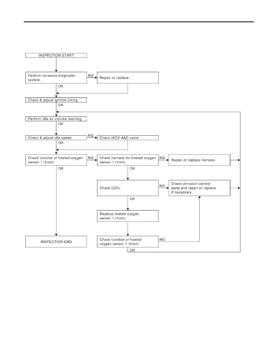
Overall Inspection Sequence
NCEC0028S0101
SEF906XA
BASIC SERVICE PROCEDURE
Idle Speed/Ignition Timing/Idle Mixture Ratio Adjustment (Cont’d)
EC-54
Нет комментариевНе стесняйтесь поделиться с нами вашим ценным мнением.
Текст