Infiniti G20 (P11). Manual — part 347
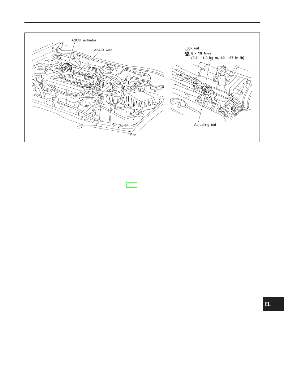
ASCD Wire Adjustment
=NCEL0101
CEL948
CAUTION:
I
Be careful not to twist ASCD wire when removing it.
I
Do not tense ASCD wire excessively during adjustment.
Adjust the tension of ASCD wire in the following manner.
1.
Loosen lock nut and adjusting nut.
2.
Make sure that accelerator wire is properly adjusted. Refer to
FE-3, “ACCELERATOR CONTROL SYSTEM”.
3.
Tighten adjusting nut just until throttle drum starts to move.
4.
Loosen adjusting nut again 1/2 to 1 turn.
5.
Tighten lock nut.
GI
MA
EM
LC
EC
FE
CL
MT
AT
AX
SU
BR
ST
RS
BT
HA
SC
IDX
AUTOMATIC SPEED CONTROL DEVICE (ASCD)
ASCD Wire Adjustment
EL-165
System Description
NCEL0102
Power is supplied at all times
I
from 30A fusible link (letter d, located in the fuse and fusible link box)
I
to circuit breaker terminal 1
I
through circuit breaker terminal 2
I
to power window relay terminal 3 and
I
to power window main switch terminal 7.
With ignition switch in ON or START position, power is supplied
I
through 10A fuse [No. 8, located in the fuse block (J/B)]
I
to power window relay terminal 1.
Ground is supplied to power window relay terminal 2
I
through body grounds M15, M71 and M76.
Then power window relay is energized and power is supplied
I
through power window relay terminal 5
I
to power window main switch terminal 11,
I
to front power window sub-switch terminal 5 and
I
to rear power window switch LH and RH terminal 5.
MANUAL OPERATION
NCEL0102S01
Front Door LH
NCEL0102S0101
Ground is supplied
I
to power window main switch terminal 6
I
through body grounds M15, M71 and M76.
WINDOW UP
When the front LH switch in the power window main switch is pulled in the up position, power is supplied
I
to front power window regulator LH terminal 3
I
through power window main switch terminal 2.
Ground is supplied
I
to front power window regulator LH terminal 1
I
through power window main switch terminal 3.
Then, the motor raises the window until the switch is released.
WINDOW DOWN
When the LH switch in the power window main switch is pressed in the down position, power is supplied
I
to front power window regulator LH terminal 1
I
through power window main switch terminal 3.
Ground is supplied
I
to front power window regulator LH terminal 3
I
through power window main switch terminal 2.
Then, the motor lowers the window until the switch is released.
Front Door RH
NCEL0102S0102
Ground is supplied
I
to power window main switch terminal 6
I
through body grounds M15, M71and M76.
NOTE:
Numbers in parentheses are terminal numbers, when power window switch is pressed in the UP and DOWN
positions respectively.
POWER WINDOW MAIN SWITCH OPERATION
Power is supplied
I
through power window main switch 4 or 5
I
to front power window switch (passenger side) 4 or 3.
POWER WINDOW
System Description
EL-166
The subsequent operation is the same as the power window switch operation.
POWER WINDOW SWITCH OPERATION
Power is supplied
I
through front power window switch (passenger side) 2 or 1
I
to front power window regulator (passenger side) 2 or 1.
Ground is supplied
I
to front power window regulator (passenger side) 1 or 2
I
through front power window switch (passenger side) 1 or 2
I
to front power window switch (passenger side) 3 or 4
I
through power window main switch 5 or 4.
Then, the motor raises or lowers the window until the switch is released.
Rear Door
NCEL0102S0103
Rear door windows will raise and lower in the same manner as front door RH window.
AUTO OPERATION
NCEL0102S02
The power window AUTO feature enables the driver to open or close the driver’s window without holding the
window switch in the down or up position.
The AUTO feature only operates on the driver’s window.
POWER WINDOW LOCK
NCEL0102S03
The power window lock is designed to lock operation of all windows except for driver’s door window.
When the lock switch is pressed to lock position, ground of the power window switches in the power window
main switch is disconnected. This prevents the power window motors from operating.
RETAINED POWER OPERATION
NCEL0102S04
When the ignition switch is turned to OFF position from ON or START position, power is supplied for 45 sec-
onds
I
to power window relay terminal 1
I
from smart entrance control unit terminal 5.
Ground is always supplied
I
to power window relay terminal 2
I
through body grounds.
When power and ground are supplied, the power window relay continues to be energized, and the power win-
dow can be operated.
The retained power operation is canceled when the driver or passenger side door is opened.
INTERRUPTION DETECTION FUNCTION
NCEL0102S05
CPU (combined with power window main switch) monitors the power window regulator motor operation and
the power window position (full closed or other) for driver’s power window by the signals from encoder and
limit switch in front power window regulator (driver’s side).
When CPU (combined with power window main switch) detects interruption during the following close opera-
tion in the driver’s side door,
I
automatic close operation when ignition switch is in the “ON” position
I
automatic close operation during retained power operation
CPU (combined with power window main switch) controls driver’s power window regulator motor for open and
the power window will be lowered about 150 mm (5.91 in).
GI
MA
EM
LC
EC
FE
CL
MT
AT
AX
SU
BR
ST
RS
BT
HA
SC
IDX
POWER WINDOW
System Description (Cont’d)
EL-167
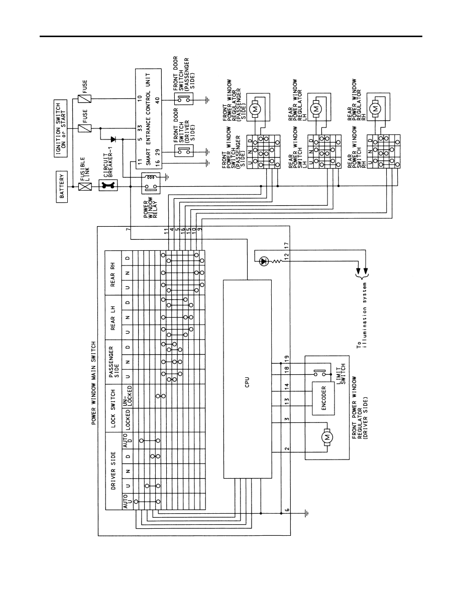
Schematic
NCEL0103
TEL525B
POWER WINDOW
Schematic
EL-168
Нет комментариевНе стесняйтесь поделиться с нами вашим ценным мнением.
Текст