Infiniti G20 (P11). Manual — part 313
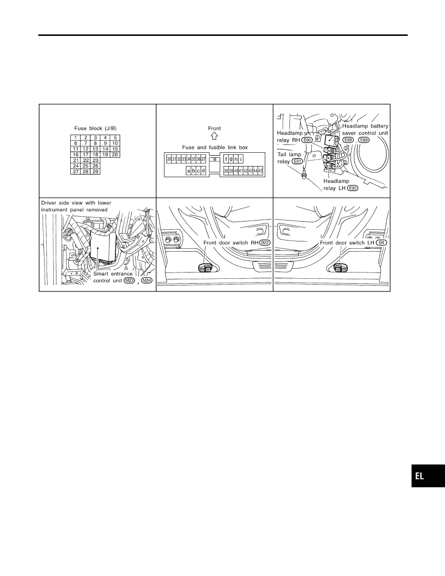
Component Parts and Harness Connector
Location
NCEL0164
SEL665W
System Description
NCEL0012
The headlamp operation is controlled by the lighting switch which is built into the combination switch and
headlamp battery saver control unit. And the headlamp battery saver system is controlled by the headlamp
battery saver control unit and smart entrance control unit.
OUTLINE
NCEL0012S04
Power is supplied at all times
I
to headlamp LH relay terminals 1 and 3
I
through 15A fuse (No. 32, located in the fuse and fusible link box), and
I
to headlamp RH relay terminals 1 and 3
I
through 15A fuse (No. 33, located in the fuse and fusible link box), and
I
to headlamp battery saver control unit terminal 7
I
through 10A fuse [No. 24, located in the fuse block (J/B)].
When the ignition switch is in the ON or START position, power is supplied
I
to headlamp battery saver control unit terminal 1
I
through 10A fuse [No. 16, located in the fuse block (J/B)], and
I
to headlamp battery saver control unit terminal 10, and
I
to smart entrance control unit terminal 33
I
through 10A fuse [No. 8, located in the fuse block (J/B)]
Ground is supplied to headlamp battery saver control unit terminals 4 and 11.
GI
MA
EM
LC
EC
FE
CL
MT
AT
AX
SU
BR
ST
RS
BT
HA
SC
IDX
HEADLAMP (FOR USA)
Component Parts and Harness Connector Location
EL-29
When Ignition Switch is in ON or START Position
NCEL0012S0401
Ground is supplied
I
to headlamp LH relay terminal 2 from headlamp battery saver control unit terminal 8
I
through headlamp battery saver control unit terminal 9, and
I
through body grounds E9 and E28, and
I
to headlamp RH relay terminal 2 from headlamp battery saver control unit terminal 2
I
through headlamp battery saver control unit terminal 3, and
I
through body grounds E9 and E28.
Headlamp relays (LH and RH) are then energized.
When Ignition Switch is in OFF or ACC Position
NCEL0012S0402
When lighting switch is in 2ND (or 1ST) position, ground is supplied
I
to headlamp battery saver control unit terminals 5 and 13
I
from lighting switch terminal 11.
And then, ground is also supplied to headlamp LH and RH relays terminal 2 from headlamp battery saver
control unit. Headlamp relays (LH and RH) are then energized.
LOW BEAM OPERATION
NCEL0012S01
When the lighting switch is turned to the 2ND position and placed in LOW (“B”) position, power is supplied
I
from lighting switch terminal 10
I
to terminal 3 of the LH headlamp, and
I
from lighting switch terminal 7
I
to terminal 3 of the RH headlamp.
Terminal 2 of each headlamp supplies ground through body grounds E9 and E28.
With power and ground supplied, the headlamp(s) will illuminate.
HIGH BEAM OPERATION/FLASH-TO-PASS OPERATION
NCEL0012S02
When the lighting switch is turned to the 2ND position and placed in HIGH (“A”) position or PASS (“C”) position,
power is supplied
I
from lighting switch terminal 6
I
to terminal 1 of the RH headlamp, and
I
from lighting switch terminal 9
I
to terminal 1 of the LH headlamp, and
I
to combination meter terminal 26 for the high beam indicator.
Ground is supplied to terminal 27 of the combination meter through body grounds M15, M71 and M76.
Terminal 2 of each headlamp supplies ground through body grounds E9 and E28.
With power and ground supplied, the high beams and the high beam indicator illuminate.
BATTERY SAVER CONTROL
NCEL0012S05
When the ignition switch is turned from ON (or START) to OFF (or ACC) positions while headlamps illuminate,
the RAP signal is supplied to terminal 10 of the headlamp battery saver control unit from smart entrance con-
trol unit terminal 5.
After counting 45 seconds by the RAP signal from the smart entrance control unit to headlamp battery saver
control unit, the ground supply to terminal 2 of the headlamp LH and RH relay from headlamp battery saver
control unit terminals 2 and 8 is terminated.
Then the headlamps are turned off.
The headlamps are turned off when driver or passenger side door is opened even if 45 seconds have not
passed after ignition switch is turned from ON (or START) to OFF (or ACC) positions while headlamps are
illuminated.
When the lighting switch is turned from OFF to 2ND after headlamps are turned to off by the battery saver
control, ground is supplied
I
to headlamp battery saver control unit terminals 5 and 13 from lighting switch terminal 11, and
I
to headlamp LH and RH relays terminal 2 from headlamp battery saver control unit terminals 2 and 8
I
through headlamp battery saver control unit terminals 3 and 9, and
I
through body grounds E9 and E28.
Then headlamps illuminate again.
HEADLAMP (FOR USA)
System Description (Cont’d)
EL-30
VEHICLE SECURITY SYSTEM
NCEL0012S03
The vehicle security system will flash the high beams if the system is triggered. Refer to “VEHICLE SECU-
RITY (THEFT WARNING) SYSTEM” (EL-216).
GI
MA
EM
LC
EC
FE
CL
MT
AT
AX
SU
BR
ST
RS
BT
HA
SC
IDX
HEADLAMP (FOR USA)
System Description (Cont’d)
EL-31
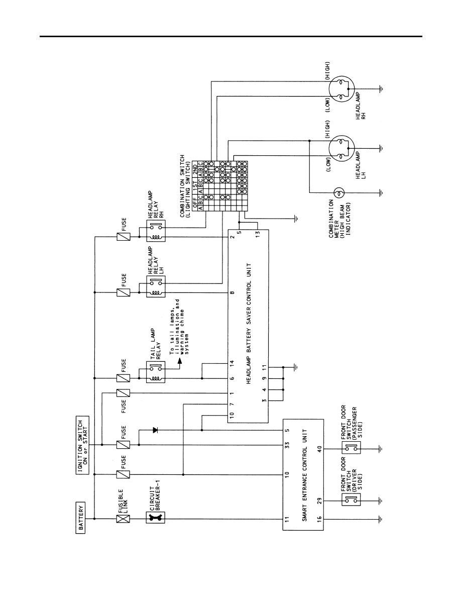
Schematic
NCEL0165
TEL474B
HEADLAMP (FOR USA)
Schematic
EL-32
Нет комментариевНе стесняйтесь поделиться с нами вашим ценным мнением.
Текст