Infiniti QX56 (JA60). Manual — part 548
FUEL TANK
FL-15
< REMOVAL AND INSTALLATION >
C
D
E
F
G
H
I
J
K
L
M
A
FL
N
P
O
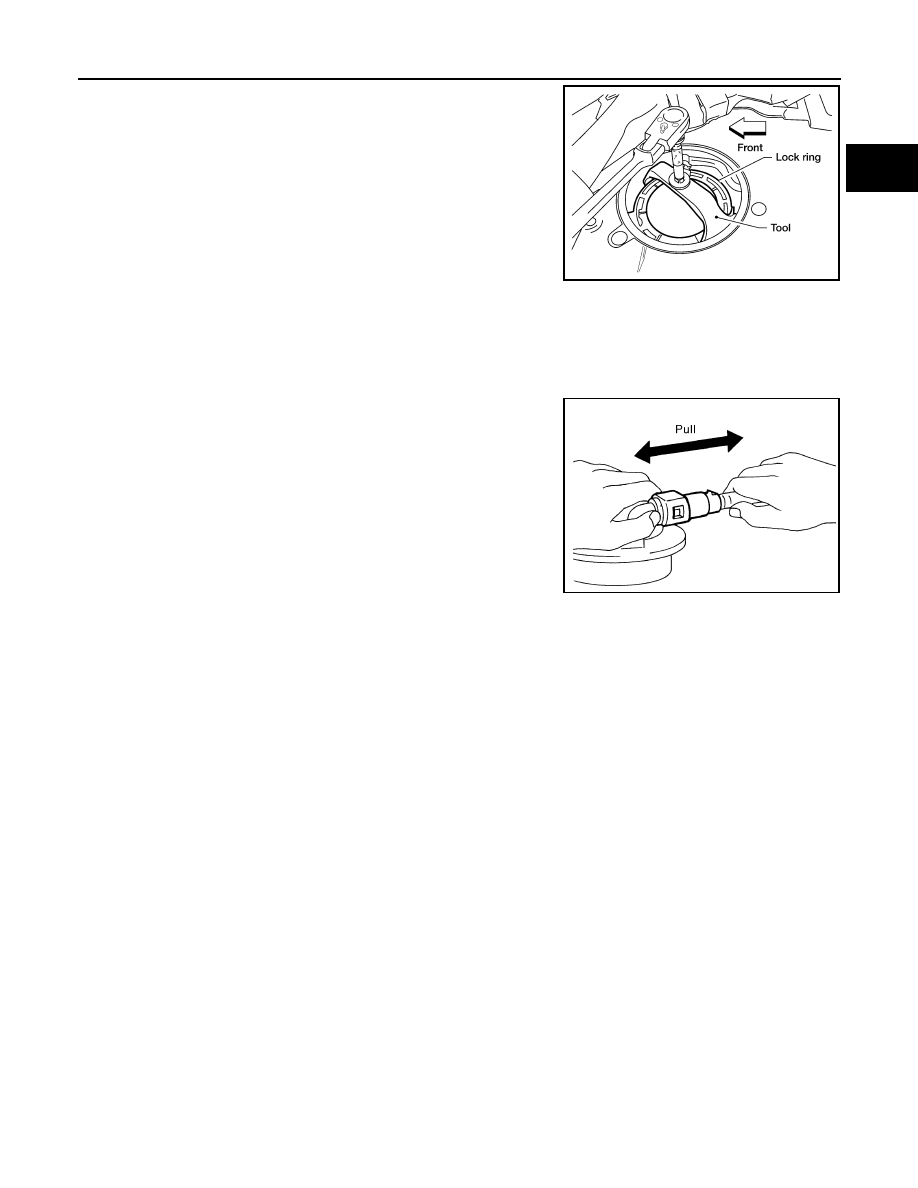
21. If necessary, remove the lock ring using Tool.
22. If necessary, remove the fuel level sensor, fuel filter, and fuel
pump assembly. Discard the fuel level sensor, fuel filter, and fuel
pump assembly O-ring.
CAUTION:
• Do not bend the float arm during removal.
• Avoid impacts such as dropping when handling the com-
ponents.
INSTALLATION
Installation is in the reverse order of removal.
• For installation, use a new fuel level sensor, fuel filter, and fuel pump assembly O-ring.
• Connect the quick connector as follows:
- Check the connection for any damage or foreign materials.
- Align the connector with the pipe, then insert the connector straight into the pipe until a click is heard.
- After connecting the quick connector, make sure that the connec-
tion is secure by checking as follows:
- Pull the tube and the connector to make sure they are securely
connected.
- Visually inspect the connector to make sure the two retainer tabs
are securely connected.
INSPECTION AFTER INSTALLATION
1. Turn the ignition switch ON but do not start engine, then check the fuel pipe and hose connections for
leaks while applying fuel pressure.
2. Start the engine and rev it above idle, then check that there are no fuel leaks at any of the fuel pipe and
hose connections.
Tool number
: — (J-46536)
LBIA0389E
PBIC1653E
FL-16
< DISASSEMBLY AND ASSEMBLY >
FUEL LEVEL SENSOR UNIT, FUEL FILTER AND FUEL PUMP ASSEMBLY
DISASSEMBLY AND ASSEMBLY
FUEL LEVEL SENSOR UNIT, FUEL FILTER AND FUEL PUMP ASSEMBLY
Disassembly and Assembly
INFOID:0000000005149536
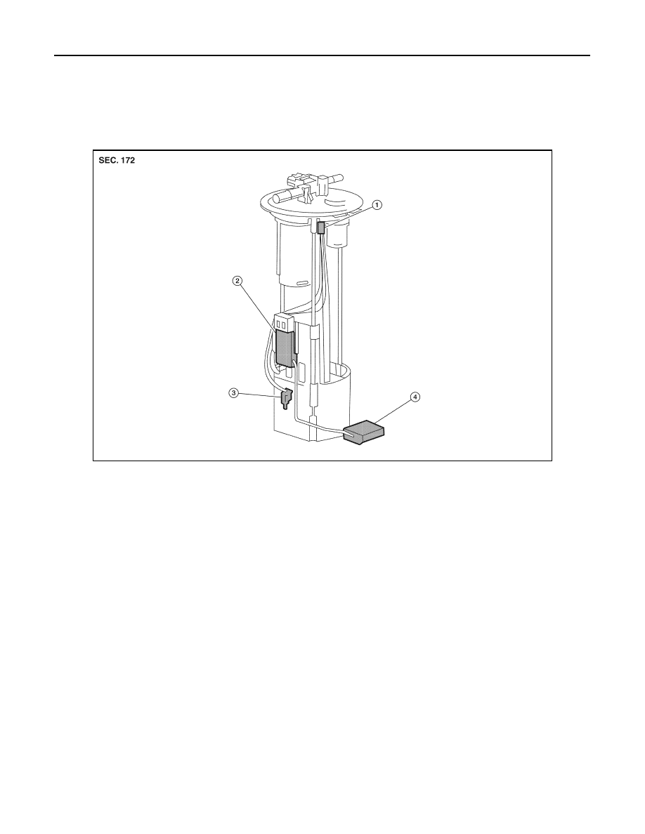
Fuel Level Sender Unit
Disassembly
1. Disconnect the harness connectors and the wire connector.
2. Remove the fuel sensor from the pump assembly.
3. Depress the tabs and remove the floater arm assembly.
Assembly
Assembly is in the reverse order of disassembly.
AWBIA0680ZZ
1.
Harness connector
2.
Sending unit module
3.
Fuel sensor
4.
Floater arm assembly
SERVICE DATA AND SPECIFICATIONS (SDS)
FL-17
< SERVICE DATA AND SPECIFICATIONS (SDS)
C
D
E
F
G
H
I
J
K
L
M
A
FL
N
P
O
SERVICE DATA AND SPECIFICATIONS (SDS)
SERVICE DATA AND SPECIFICATIONS (SDS)
Standard and Limit
INFOID:0000000005149537
Unit: (US gal, Imp gal)
Fuel tank capacity
105.8 (28, 23 1/4)
FSU-1
SUSPENSION
C
D
F
G
H
I
J
K
L
M
SECTION
FSU
A
B
FSU
N
O
P
CONTENTS
FRONT SUSPENSION
PRECAUTION . . . . . . . . . . . ...
PRECAUTIONS . . . . . . . . . . . . ...
Precaution Necessary for Steering Wheel Rota-
tion After Battery Disconnect . . . . . . . . .....
Precaution . . . . . . . . . . . . . . . .....
PREPARATION . . . . . . . . . . .
PREPARATION . . . . . . . . . . . . ...
Special Service Tool . . . . . . . . . . . .....
Commercial Service Tool . . . . . . . . . . ..
SYMPTOM DIAGNOSIS . . . . . . . ...
NOISE, VIBRATION AND HARSHNESS
(NVH) TROUBLESHOOTING . . . . . . . .
NVH Troubleshooting Chart . . . . . . . . . ..
ON-VEHICLE MAINTENANCE . . . . . .
ON-VEHICLE SERVICE . . . . . . . . . ..
Front Suspension Parts . . . . . . . . . . .....
Front Wheel Alignment . . . . . . . . . . . ..
UPPER BALL JOINT AND LOWER BALL
JOINT . . . . . . . . . . . . . . . . .
Inspection . . . . . . . . . . . . . . . .
KNUCKLE . . . . . . . . . . . . . . ..
On-Vehicle Inspection and Service . . . . . . .
ON-VEHICLE REPAIR . . . . . . . . .
FRONT SUSPENSION ASSEMBLY . . . . ..
Component . . . . . . . . . . . . . . . ..
REMOVAL AND INSTALLATION . . . ...
COIL SPRING AND SHOCK ABSORBER . ...
Removal and Installation . . . . . . . . . . .
Disposal . . . . . . . . . . . . . . . . ...
STABILIZER BAR . . . . . . . . . . . .
Removal and Installation . . . . . . . . . . .
UPPER LINK . . . . . . . . . . . . . .
Removal and Installation . . . . . . . . . . .
LOWER LINK . . . . . . . . . . . . .
Removal and Installation . . . . . . . . . . .
UPPER BALL JOINT AND LOWER BALL
JOINT . . . . . . . . . . . . . . . .
Removal and Installation . . . . . . . . . . .
KNUCKLE . . . . . . . . . . . . . . .
Removal and Installation . . . . . . . . . . .
DISASSEMBLY AND ASSEMBLY . . . ..
COIL SPRING AND SHOCK ABSORBER . ...
Disassembly and Assembly . . . . . . . . . .
SERVICE DATA AND SPECIFICATIONS
(SDS) . . . . . . . . . . . . . . .
SERVICE DATA AND SPECIFICATIONS
(SDS) . . . . . . . . . . . . . . . . .
General Specification . . . . . . . . . . . ..
Spring Free Height . . . . . . . . . . . . ..
Нет комментариевНе стесняйтесь поделиться с нами вашим ценным мнением.
Текст