Infiniti QX56 (JA60). Manual — part 129
C1101, C1102, C1103, C1104 WHEEL SENSOR-1
BRC-29
< COMPONENT DIAGNOSIS >
[VDC/TCS/ABS]
C
D
E
G
H
I
J
K
L
M
A
B
BRC
N
O
P
NOTE:
The green POWER indicator should illuminate. If the POWER indicator does not illuminate, replace the
battery in the ABS active wheel sensor tester before proceeding.
3. Spin the wheel of the vehicle by hand and observe the red SENSOR indicator on the ABS active wheel
sensor tester. The red SENSOR indicator should flash on and off to indicate an output signal.
NOTE:
If the red SENSOR indicator illuminates but does not flash, reverse the polarity of the tester leads and
retest.
Does the ABS active wheel sensor tester detect a signal?
YES
>> GO TO 3
NO
>> Replace the wheel sensor. Refer to
BRC-114, "Removal and Installation"
3.
CHECK TIRES
Check the inflation pressure, wear and size of each tire.
Is the inspection result normal?
YES
>> GO TO 4
NO
>> Adjust tire pressure or replace tire(s).
4.
CHECK WHEEL BEARINGS
Check wheel bearing axial end play. Refer to
FAX-6, "On-Vehicle Inspection and Service"
"On-Vehicle Inspection and Service"
(rear).
Is the inspection result normal?
YES
>> GO TO 5
NO
>> Repair or replace as necessary. Refer to
FAX-7, "Removal and Installation"
(rear).
5.
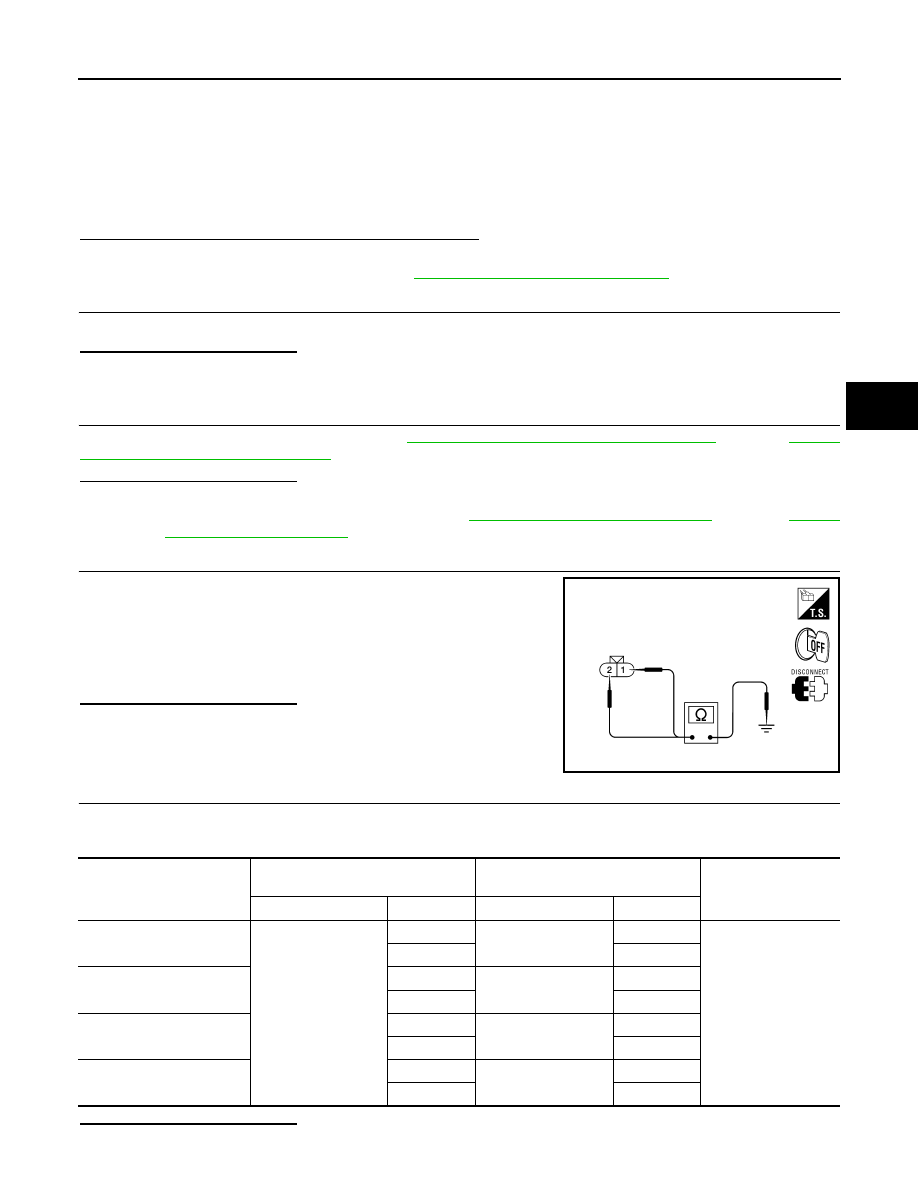
CHECK WIRING HARNESS FOR SHORT CIRCUIT
1. Disconnect ABS actuator and electric unit (control unit) connec-
tor and wheel sensor connector of malfunction code.
2. Check continuity between wheel sensor connector terminals
and ground.
Is the inspection result normal?
YES
>> GO TO 6
NO
>> Repair the circuit.
6.
CHECK WIRING HARNESS FOR OPEN CIRCUIT
Check continuity between ABS actuator and electric unit (control unit) connector and the malfunctioning wheel
sensor connector.
Is the inspection result normal?
Continuity should not exist.
AWFIA0188ZZ
Wheel sensor
ABS actuator and
electric unit (control unit)
Wheel sensor
Continuity
Connector
Terminal
Connector
Terminal
Front LH
E125
45
E18
1
Yes
46
2
Front RH
34
E117
1
33
2
Rear LH
37
C11
2
36
1
Rear RH
42
C10
2
43
1

BRC-30
< COMPONENT DIAGNOSIS >
[VDC/TCS/ABS]
C1101, C1102, C1103, C1104 WHEEL SENSOR-1
YES
>> Replace the ABS actuator and electric unit (control unit). Refer to
.
NO
>> Repair the circuit.
Component Inspection
INFOID:0000000005147966
1.
CHECK DATA MONITOR
On “DATA MONITOR”, select “FR LH SENSOR”, “FR RH SENSOR”, “RR LH SENSOR”, and “RR RH SEN-
SOR”, and check the vehicle speed.
Is the inspection result normal?
YES
>> Inspection End
NO
>> Go to diagnosis procedure. Refer to
Special Repair Requirement
INFOID:0000000005147967
1.
ADJUSTMENT OF STEERING ANGLE SENSOR NEUTRAL POSITION
Always perform neutral position adjustment for the steering angle sensor when replacing the ABS actuator
and electric unit (control unit). Refer to
BRC-8, "ADJUSTMENT OF STEERING ANGLE SENSOR NEUTRAL
.
>> GO TO 2
2.
CALIBRATION OF DECEL G SENSOR
Always perform calibration of decel G sensor when replacing the ABS actuator and electric unit (control unit).
BRC-9, "CALIBRATION OF DECEL G SENSOR : Description"
>> END
Wheel sensor
Vehicle speed (DATA MONITOR)
FR LH SENSOR
Nearly matches the speedometer dis-
play (
±10% or less)
FR RH SENSOR
RR LH SENSOR
RR RH SENSOR
C1105, C1106, C1107, C1108 WHEEL SENSOR-2
BRC-31
< COMPONENT DIAGNOSIS >
[VDC/TCS/ABS]
C
D
E
G
H
I
J
K
L
M
A
B
BRC
N
O
P
C1105, C1106, C1107, C1108 WHEEL SENSOR-2
Description
INFOID:0000000005147968
When the sensor rotor rotates, the magnetic field changes. It converts the magnetic field changes to current
signals (rectangular wave) and transmits them to the ABS actuator and electric unit (control unit).
DTC Logic
INFOID:0000000005147969
DTC DETECTION LOGIC
DTC CONFIRMATION PROCEDURE
1.
CHECK SELF-DIAGNOSIS RESULTS
Check the self-diagnosis results.
Is above displayed on the self-diagnosis display?
YES
>> Proceed to diagnosis procedure. Refer to
.
NO
>> Inspection End
Diagnosis Procedure
INFOID:0000000005194911
Regarding Wiring Diagram information, refer to
BRC-92, "Wiring Diagram - BRAKE CONTROL SYSTEM -"
CAUTION:
Do not check between wheel sensor terminals.
1.
CONNECTOR INSPECTION
1. Disconnect the ABS actuator and electric unit (control unit) connector and wheel sensor of malfunctioning
code.
2. Check the terminals for deformation, disconnection, looseness or damage.
Is the inspection result normal?
YES
>> GO TO 2
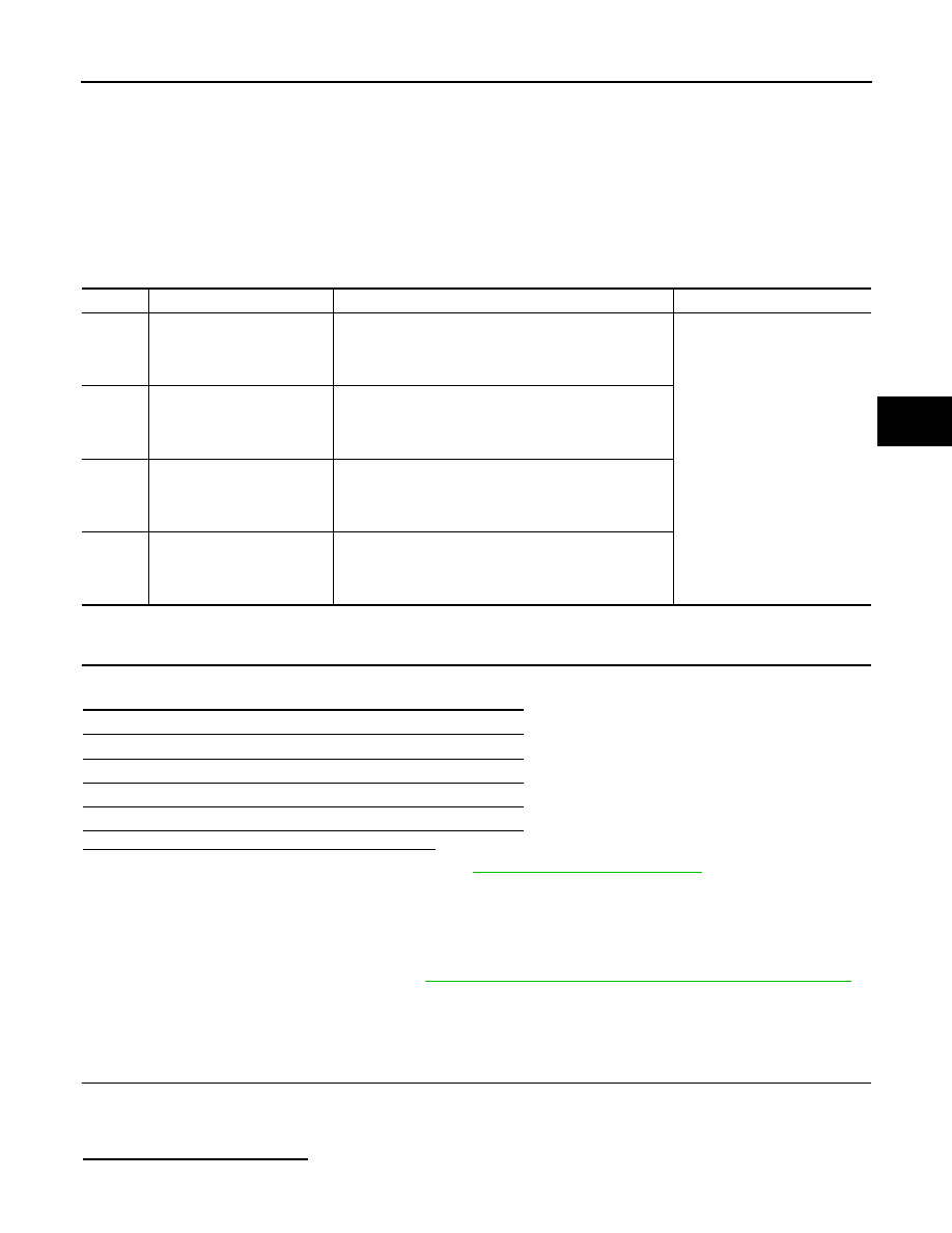
DTC
Display item
Malfunction detected condition
Possible cause
C1105
RR RH SENSOR-2
When the circuit in the rear RH wheel sensor is short-cir-
cuited. Or when the distance between the wheel sensor
and sensor rotor is too large and the sensor pulse cannot
be recognized by the control unit.
• Harness or connector
• Wheel sensor
• ABS actuator and electric unit
(control unit)
C1106
RR LH SENSOR-2
When the circuit in the rear LH wheel sensor is short-cir-
cuited. Or when the distance between the wheel sensor
and sensor rotor is too large and the sensor pulse cannot
be recognized by the control unit.
C1107
FR RH SENSOR-2
When the circuit in the front RH wheel sensor is short-cir-
cuited. Or when the distance between the wheel sensor
and sensor rotor is too large and the sensor pulse cannot
be recognized by the control unit.
C1108
FR LH SENSOR-2
When the circuit in the front LH wheel sensor is short-cir-
cuited. Or when the distance between the wheel sensor
and sensor rotor is too large and the sensor pulse cannot
be recognized by the control unit.
Self-diagnosis results
RR RH SENSOR-2
RR LH SENSOR-2
FR RH SENSOR-2
FR LH SENSOR-2
BRC-32
< COMPONENT DIAGNOSIS >
[VDC/TCS/ABS]
C1105, C1106, C1107, C1108 WHEEL SENSOR-2
NO
>> Repair or replace as necessary.
2.
CHECK WHEEL SENSOR OUTPUT SIGNAL
1. Connect ABS active wheel sensor tester (J-45741) to wheel sensor using appropriate adapter.
2. Turn on the ABS active wheel sensor tester power switch.
NOTE:
The green POWER indicator should illuminate. If the POWER indicator does not illuminate, replace the
battery in the ABS active wheel sensor tester before proceeding.
3. Spin the wheel of the vehicle by hand and observe the red SENSOR indicator on the ABS active wheel
sensor tester. The red SENSOR indicator should flash on and off to indicate an output signal.
NOTE:
If the red SENSOR indicator illuminates but does not flash, reverse the polarity of the tester leads and
retest.
Does the ABS active wheel sensor tester detect a signal?
YES
>> GO TO 3
NO
>> Replace the wheel sensor. Refer to
BRC-114, "Removal and Installation"
3.
CHECK TIRES
Check the inflation pressure, wear and size of each tire.
Is the inspection result normal?
YES
>> GO TO 4
NO
>> Adjust tire pressure or replace tire(s).
4.
CHECK WHEEL BEARINGS
Check wheel bearing axial end play. Refer to
FAX-6, "On-Vehicle Inspection and Service"
"On-Vehicle Inspection and Service"
(rear).
Is the inspection result normal?
YES
>> GO TO 5
NO
>> Repair or replace as necessary. Refer to
FAX-7, "Removal and Installation"
(front) or
(rear).
5.
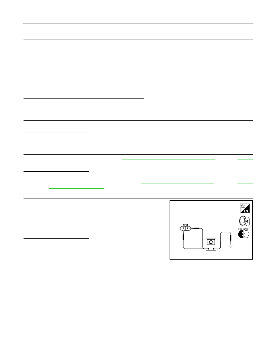
CHECK WIRING HARNESS FOR SHORT CIRCUIT
1. Disconnect ABS actuator and electric unit (control unit) connec-
tor and wheel sensor connector of malfunction code.
2. Check continuity between wheel sensor connector terminals
and ground.
Is the inspection result normal?
YES
>> GO TO 6
NO
>> Repair the circuit.
6.
CHECK WIRING HARNESS FOR OPEN CIRCUIT
Check continuity between ABS actuator and electric unit (control unit) connector and the malfunctioning wheel
sensor connector.
Continuity should not exist.
AWFIA0188ZZ
Нет комментариевНе стесняйтесь поделиться с нами вашим ценным мнением.
Текст