Infiniti QX56 (JA60). Manual — part 995
VARIABLE BLOWER CONTROL
VTL-15
< ON-VEHICLE REPAIR >
C
D
E
F
G
H
J
K
L
M
A
B
VTL
N
O
P
Rear Variable Blower Control - Rear Heater and Cooling Unit Assembly
Removal and Installation
INFOID:0000000005147623
FRONT VARIABLE BLOWER CONTROL
Removal
1. Remove the glove box assembly. Refer to
IP-17, "Removal and Installation"
2. Disconnect the variable blower control electrical connector.
3. Remove the two screws and remove the variable blower control.
Installation
Installation is in the reverse order of removal.
REAR VARIABLE BLOWER CONTROL
Removal
1. Remove the luggage side finisher lower RH. Refer to
INT-19, "Removal and Installation"
.
2. Disconnect the rear blower motor resistor electrical connector.
3. Remove the two screws and remove the rear blower motor resistor.
Installation
Installation is in the reverse order of removal.
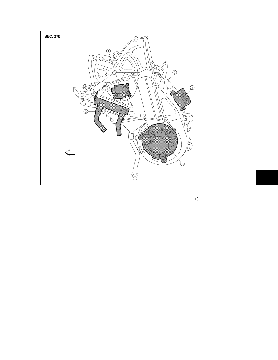
ALIIA0066ZZ
1.
Air mix door motor
2.
Heater core
3.
Blower motor
4.
Variable blower control
5.
Rear heater and cooling unit assembly
Front
VTL-16
< ON-VEHICLE REPAIR >
HEATER & COOLING UNIT ASSEMBLY
HEATER & COOLING UNIT ASSEMBLY
Component
INFOID:0000000005147612
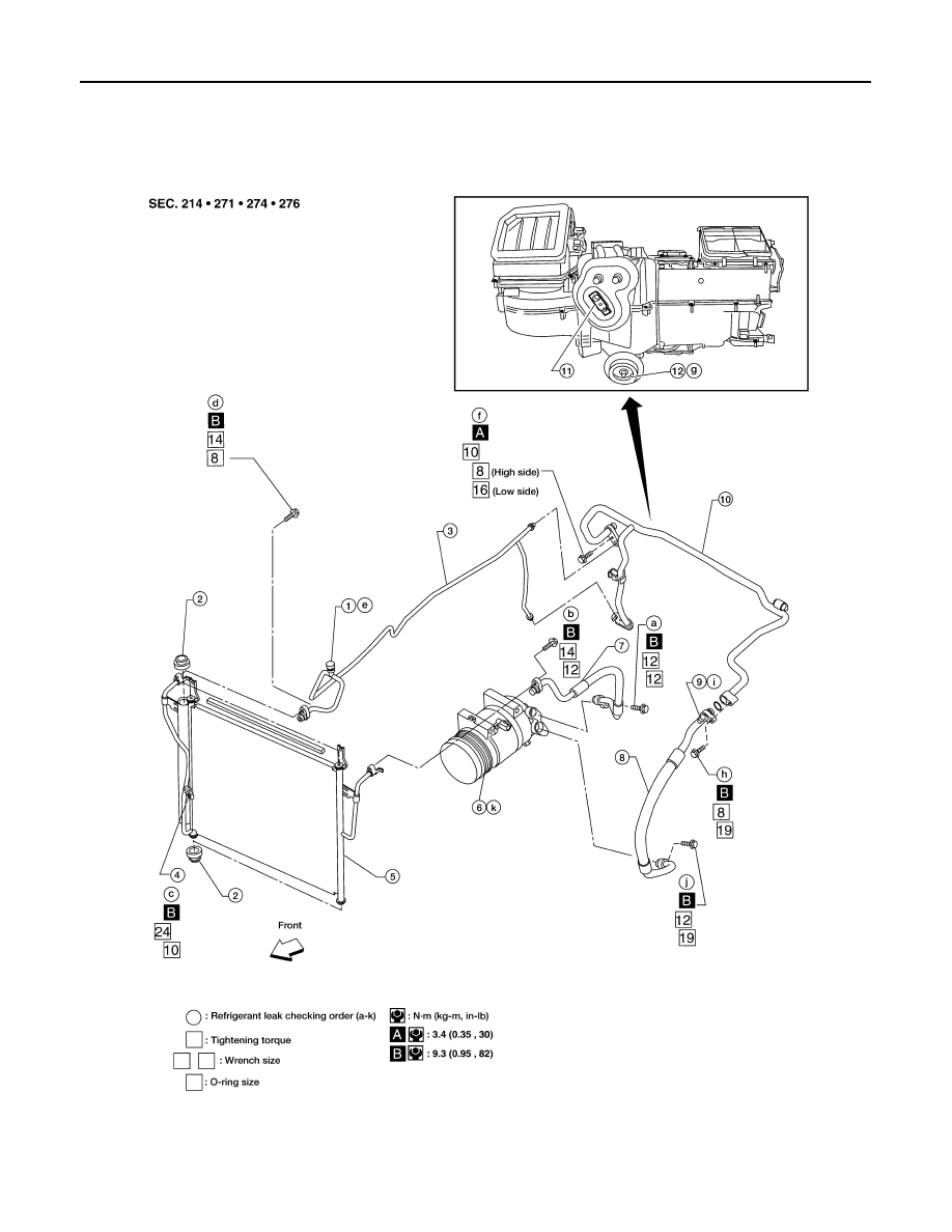
Front A/C System
WJIA1578E
1.
High-pressure service valve
2.
Grommet
3.
High-pressure pipe
4.
Refrigerant pressure sensor
5.
Condenser
6.
Compressor shaft seal
HEATER & COOLING UNIT ASSEMBLY
VTL-17
< ON-VEHICLE REPAIR >
C
D
E
F
G
H
J
K
L
M
A
B
VTL
N
O
P
Rear A/C System
NOTE:
HA-5, "Precaution for Refrigerant Connection"
Removal and Installation
INFOID:0000000005147613
FRONT HEATER AND COOLING UNIT ASSEMBLY
Removal
7.
High-pressure flexible hose
8.
Low-pressure flexible hose
9.
Low-pressure service valve
10. Low-pressure pipe
11. Expansion valve (front)
12. Drain hose
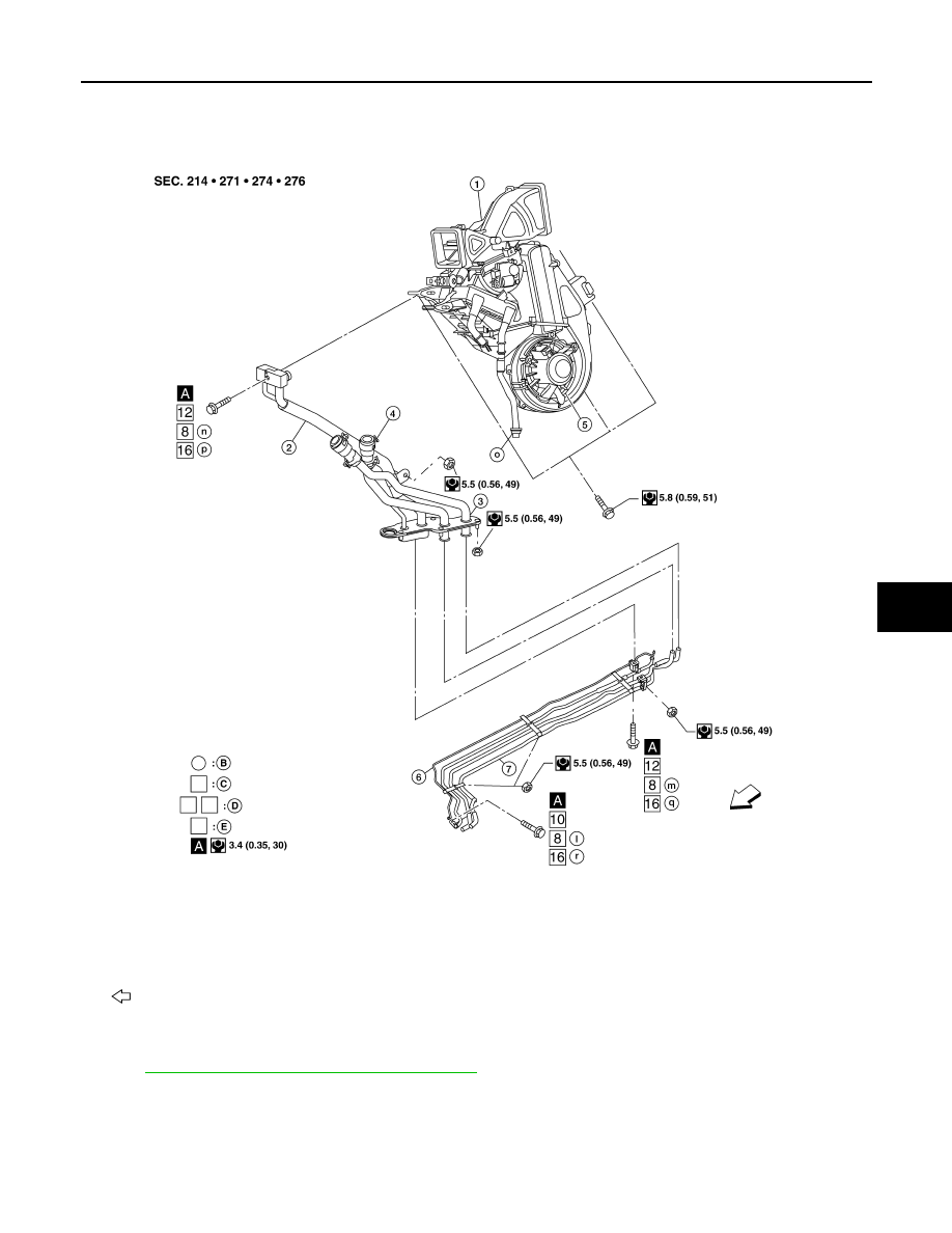
AWIIA0134GB
1.
Rear heater and cooling unit assembly 2.
Rear A/C pipes
3.
Rear A/C heater core pipes
4.
Rear heater core hose
5.
Rear blower motor
6.
Underfloor rear A/C pipes
7.
Underfloor rear heater core pipes
A.
Bolt torque specification
B.
Leak checking order (l - r)
C.
Tightening torque
D.
Wrench size
E.
O-ring size
Front
NOTE: The O-ring size 8 is the high-side and the O-ring size 16 is the low-side.

VTL-18
< ON-VEHICLE REPAIR >
HEATER & COOLING UNIT ASSEMBLY
1. Move the two front seats to the rear most position on the seat track.
2. Disconnect the battery negative terminal and battery positive terminal.
3. Discharge the refrigerant from the A/C system. Refer to
HA-20, "HFC-134a (R-134a) Service Procedure"
4. Drain the coolant from the engine cooling system. Refer to
CO-11, "Changing Engine Coolant"
.
5. Disconnect the front heater hoses from the front heater core.
6. Disconnect the high/low pressure pipes from the front expansion valve.
7. Remove the instrument panel and console panel. Refer to
IP-12, "Removal and Installation"
8. Disconnect the instrument panel wire harness at the RH and LH in-line connector brackets, and the fuse
block (J/B) electrical connectors. Refer to
PG-9, "Wiring Diagram — Battery Power Supply —"
9. Disconnect the steering member from each side of the vehicle body.
10. Remove the front heater and cooling unit assembly with it attached to the steering member, from the vehi-
cle.
CAUTION:
Use care not to damage the seats and interior trim panels when removing the front heater and
cooling unit assembly with it attached to the steering member.
11. Remove the front heater and cooling unit assembly from the steering member.
Installation
Installation is in the reverse order of removal.
CAUTION:
• Replace the O-ring of the low-pressure pipe and high-pressure pipe with a new one, and apply com-
pressor oil to it when installing it.
• After charging the refrigerant, check for leaks.
NOTE:
• Fill the engine cooling system with the specified coolant mixture. Refer to
.
• Recharge the A/C system. Refer to
HA-20, "HFC-134a (R-134a) Service Procedure"
.
REAR HEATER AND COOLING UNIT ASSEMBLY
Removal
1. Discharge the refrigerant from the A/C system. Refer to
HA-20, "HFC-134a (R-134a) Service Procedure"
2. Drain the coolant from the engine cooling system. Refer to
CO-11, "Changing Engine Coolant"
.
3. Remove the luggage side finisher lower and upper RH. Refer to
INT-19, "Removal and Installation"
4. Disconnect the rear heater core hoses from the rear heater core.
5. Disconnect the rear A/C pipes from the rear expansion valve.
6. Disconnect the following electrical connectors:
• Rear blower motor
• Rear variable blower control
• Rear air mix door motor
• Rear mode door motor
7. Disconnect the ducts and drain tube from the rear heater and cooling unit assembly.
8. Remove the rear heater and cooling unit assembly.
Installation
Installation is in the reverse order of removal.
CAUTION:
• Replace the O-ring of the low-pressure pipe and high-pressure pipe with a new one, and apply com-
pressor oil to it when installing it.
• After charging the refrigerant, check for leaks.
NOTE:
• Fill the engine cooling system with the specified coolant mixture. Refer to
.
• Recharge the A/C system. Refer to
HA-20, "HFC-134a (R-134a) Service Procedure"
.
Нет комментариевНе стесняйтесь поделиться с нами вашим ценным мнением.
Текст