Infiniti QX56 (JA60). Manual — part 591
DIAGNOSIS SYSTEM (BCM)
HAC-21
< FUNCTION DIAGNOSIS >
[AUTOMATIC AIR CONDITIONER]
C
D
E
F
G
H
J
K
L
M
A
B
HAC
N
O
P
DIAGNOSIS SYSTEM (BCM)
CONSULT-III Function (BCM - COMMON ITEM)
INFOID:0000000005273928
APPLICATION ITEM
CONSULT-III performs the following functions via CAN communication with BCM.
SYSTEM APPLICATION
BCM can perform the following functions for each system.
NOTE:
It can perform the diagnosis modes except the following for all sub system selection items.
CONSULT-III Function (BCM - AIR CONDITIONER)
INFOID:0000000005273929
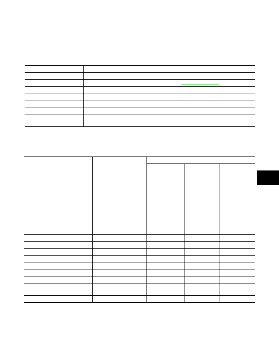
DATA MONITOR
Diagnosis mode
Function Description
WORK SUPPORT
Changes the setting for each system function.
SELF-DIAG RESULTS
Displays the diagnosis results judged by BCM. Refer to
CAN DIAG SUPPORT MNTR
Monitors the reception status of CAN communication viewed from BCM.
DATA MONITOR
The BCM input/output signals are displayed.
ACTIVE TEST
The signals used to activate each device are forcibly supplied from BCM.
ECU IDENTIFICATION
The BCM part number is displayed.
CONFIGURATION
• Enables to read and save the vehicle specification.
• Enables to write the vehicle specification when replacing BCM.
System
Sub system selection item
Diagnosis mode
WORK SUPPORT
DATA MONITOR
ACTIVE TEST
BCM
BCM
×
Door lock
DOOR LOCK
×
×
×
Rear window defogger
REAR DEFOGGER
×
Warning chime
BUZZER
×
×
Interior room lamp timer
INT LAMP
×
×
×
Exterior lamp
HEAD LAMP
×
×
×
Wiper and washer
WIPER
×
×
×
Turn signal and hazard warning lamps FLASHER
×
×
Air conditioner
AIR CONDITONER
×
Intelligent Key system
INTELLIGENT KEY
×
Combination switch
COMB SW
×
Immobilizer
IMMU
×
×
Interior room lamp battery saver
BATTERY SAVER
×
×
×
Back door open
TRUNK
×
×
RAP (retained accessory power)
RETAINED PWR
×
×
×
Signal buffer system
SIGNAL BUFFER
×
×
TPMS (tire pressure monitoring sys-
tem)
AIR PRESSURE MONITOR
×
×
×
Panic alarm system
PANIC ALARM
×

HAC-22
< FUNCTION DIAGNOSIS >
[AUTOMATIC AIR CONDITIONER]
DIAGNOSIS SYSTEM (BCM)
Monitor Item
[Unit]
Contents
IGN ON SW [ON/OFF]
Display [ignition switch position (On)/(Off), ACC position (Off)] status as judged from ignition
switch signal
FAN ON SIG [ON/OFF]
Display [FAN (On)/FAN (Off)] status as judged form blower fan motor switch signal
AIR COND SW [ON/OFF]
Display [COMP (On)/COMP (Off)] status as judged form air conditioner switch signal
SELF-DIAGNOSIS FUNCTION
HAC-23
< FUNCTION DIAGNOSIS >
[AUTOMATIC AIR CONDITIONER]
C
D
E
F
G
H
J
K
L
M
A
B
HAC
N
O
P
SELF-DIAGNOSIS FUNCTION
A/C Auto Amp. Self-Diagnosis
INFOID:0000000005147684
A/C SYSTEM SELF-DIAGNOSIS FUNCTION
The self-diagnosis function is built into the A/C auto amp. to quickly locate the cause of malfunctions.
DESCRIPTION
The self-diagnostic system diagnoses sensors, CAN system, and battery voltage on A/C auto amp. Refer to
applicable sections (items) for details. Fault codes (if any are present) will be displayed in the ambient temper-
ature display area. Refer to
HAC-24, "A/C System Self-Diagnosis Code Chart"
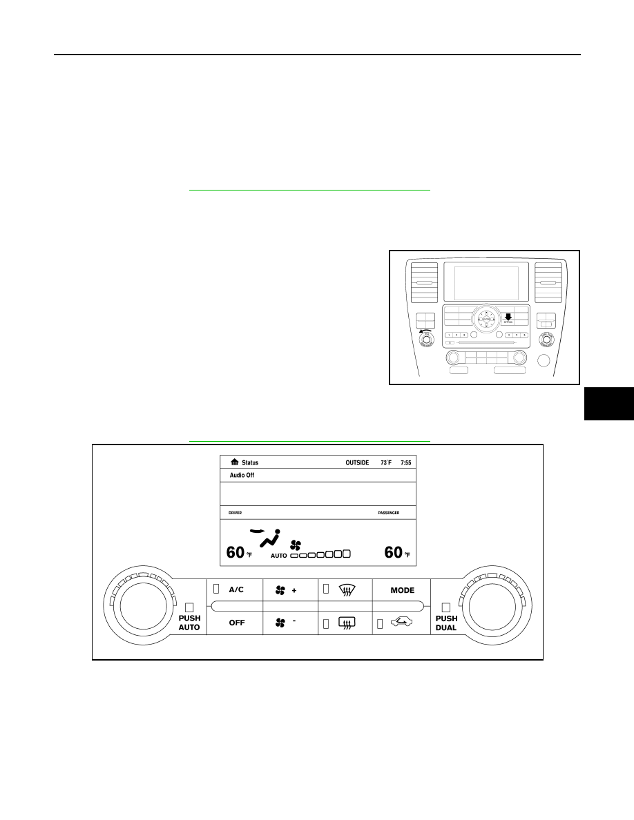
SELF-DIAGNOSTIC MODE
NOTE:
Radio must be off.
1. On the A/C and AV switch assembly, press the "SETTING" but-
ton and twist the volume knob clockwise and counterclockwise
until the Self-Diagnosis screen shows on the display.
2. Scroll down to "Confirmation/Adjustment" and press the
"ENTER" button.
3. Scroll down to "Climate Control" and press the "ENTER" button.
4. The fan bars will flash on the display during the self-test, and
then the fault codes will display in the ambient temperature area.
They will continue scrolling until diagnostic mode is exited.
5. Exit by pressing the "BACK" button on A/C and AV switch
assembly until display returns to its normal operation screen.
HVAC system will be OFF.
The self-diagnostic system diagnoses sensors, CAN system, and battery voltage on A/C auto amp. Refer to
applicable sections (items) for details. Fault codes (if any are present) will be displayed in the ambient temper-
ature display area. Refer to
HAC-24, "A/C System Self-Diagnosis Code Chart"
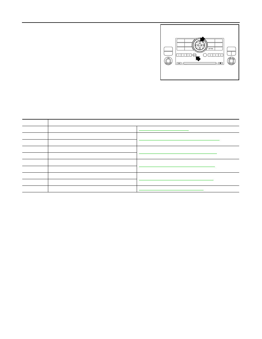
A/C and AV Switch Assembly Self-Diagnosis
INFOID:0000000005147685
A/C and AV switch assembly self-diagnosis function
The ON/OFF operation (continuity) of each switch in the A/C and AV switch assembly can be checked.
Self-diagnosis mode
AWNIA0098ZZ
AWIIA0081ZZ
HAC-24
< FUNCTION DIAGNOSIS >
[AUTOMATIC AIR CONDITIONER]
SELF-DIAGNOSIS FUNCTION
• Press the “BACK” switch and the “UP” switch within 10 seconds
after turning the ignition switch from OFF to ACC and hold them for
3 seconds or more. Then the buzzer sounds, all indicators of the
preset switch illuminate, and the self-diagnosis mode starts.
• The continuity of each switch and control dials (A/C and AV switch
assembly only) at the ON position can be checked by pressing
each switch and turning each control dial. The buzzer sounds and
LED’s will illuminate if the switch is normal.
Finishing self-diagnosis mode
Self-diagnosis mode is canceled when turning the ignition switch OFF.
A/C System Self-Diagnosis Code Chart
INFOID:0000000005147686
SELF-DIAGNOSTIC CODE CHART
AWIIA0171GB
Code No.
Reference page
03
Battery voltage out of range
30
In-vehicle sensor circuit out of range (low)
HAC-78, "In-Vehicle Sensor Diagnosis Procedure"
31
In-vehicle sensor circuit out of range (high)
40
Ambient sensor circuit short
HAC-75, "Ambient Sensor Diagnosis Procedure"
41
Ambient sensor circuit open
50
Optical sensor (Driver) circuit open or short
HAC-81, "Optical Sensor Diagnosis Procedure"
52
Optical sensor (Passenger) circuit open or short
56
Intake sensor circuit short
HAC-83, "Intake Sensor Diagnosis Procedure"
57
Intake sensor circuit open
80
CAN bus fault
Нет комментариевНе стесняйтесь поделиться с нами вашим ценным мнением.
Текст