Infiniti QX56 (JA60). Manual — part 124

INSPECTION AND ADJUSTMENT
BRC-9
< BASIC INSPECTION >
[VDC/TCS/ABS]
C
D
E
G
H
I
J
K
L
M
A
B
BRC
N
O
P
>> GO TO 2
2.
PERFORM THE NEUTRAL POSITION ADJUSTMENT FOR THE STEERING ANGLE SENSOR
1. On the CONSULT-III screen, touch “WORK SUPPORT” and “ST ANG SEN ADJUSTMENT” in order.
2. Touch “START”.
CAUTION:
Do not touch steering wheel while adjusting steering angle sensor.
3. After approximately 10 seconds, touch “END”.
NOTE:
After approximately 60 seconds, it ends automatically.
4. Turn ignition switch OFF, then turn it ON again.
CAUTION:
Be sure to perform above operation.
>> GO TO 3
3.
CHECK DATA MONITOR
1. Run vehicle with front wheels in straight-ahead position, then stop.
2. Select “DATA MONITOR”. Then make sure “STR ANGLE SIG” is within 0
±2.5°.
Is the steering angle within the specified range?
YES
>> GO TO 4
NO
>> Perform the neutral position adjustment for the steering angle sensor again, GO TO 1
4.
ERASE THE SELF-DIAGNOSIS MEMORY
Erase the self-diagnosis memory of the ABS actuator and electric unit (control unit) and ECM.
• ABS actuator and electric unit (control unit): Refer to
BRC-23, "CONSULT-III Function (ABS)"
.
• ECM: Refer to
EC-63, "CONSULT-III Function (ENGINE)"
.
Are the memories erased?
YES
>> Inspection End
NO
>> Check the items indicated by the self-diagnosis.
CALIBRATION OF DECEL G SENSOR
CALIBRATION OF DECEL G SENSOR : Description
INFOID:0000000005147944
Refer to the table below to determine if calibration of the decel G sensor is required.
×: Required –: Not required
CALIBRATION OF DECEL G SENSOR : Special Repair Requirement
INFOID:0000000005147945
CALIBRATION OF DECEL G SENSOR
CAUTION:
To calibrate the decel G sensor, make sure to use CONSULT-III
Situation
Calibration of decel G sensor
Removing/Installing ABS actuator and electric unit (control unit)
—
Replacing ABS actuator and electric unit (control unit)
×
Removing/Installing steering angle sensor
×
Replacing steering angle sensor
×
Removing/Installing steering components
×
Replacing steering components
×
Removing/Installing suspension components
×
Replacing suspension components
×
Change tires to new ones
—
Tire rotation
—
Adjusting wheel alignment
×

BRC-10
< BASIC INSPECTION >
[VDC/TCS/ABS]
INSPECTION AND ADJUSTMENT
(Calibration cannot be done without CONSULT-III)
1.
ALIGN THE VEHICLE STATUS
Stop vehicle with front wheels in straight-ahead position.
>> GO TO 2
2.
PERFORM CALIBRATION OF DECEL G SENSOR
1. On the CONSULT-III screen, touch “WORK SUPPORT” and “DECEL G SEN CALIBRATION” in order.
2. Touch “START”.
3. After approximately 10 seconds, touch “END”.
NOTE:
After approximately 60 seconds, it ends automatically.
4. Turn ignition switch OFF, then turn it ON again.
CAUTION:
Be sure to perform above operation.
>> GO TO 3
3.
CHECK DATA MONITOR
1. Run vehicle with front wheels in straight-ahead position, then stop.
2. Select “DATA MONITOR”. Then make sure “DECEL G SEN” is within
± 0.08G.
Is the inspection result normal?
YES
>> GO TO 4
NO
>> Perform calibration of decel G sensor again, GO TO 1
4.
ERASE THE SELF-DIAGNOSIS MEMORY
Erase the self-diagnosis memory of the ABS actuator and electric unit (control unit) and ECM.
• ABS actuator and electric unit (control unit): Refer to
BRC-23, "CONSULT-III Function (ABS)"
.
• ECM: Refer to
EC-63, "CONSULT-III Function (ENGINE)"
.
Are the memories erased?
YES
>> Inspection End
NO
>> Check the items indicated by the self-diagnosis.
VDC
BRC-11
< FUNCTION DIAGNOSIS >
[VDC/TCS/ABS]
C
D
E
G
H
I
J
K
L
M
A
B
BRC
N
O
P
FUNCTION DIAGNOSIS
VDC
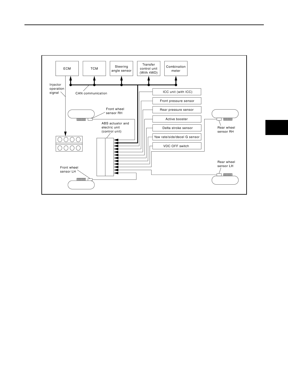
System Diagram
INFOID:0000000005147946
System Description
INFOID:0000000005147947
• Vehicle Dynamics Control system detects driver
′s steering operation amount and brake pedal travel from
steering angle sensor and pressure sensors. Using information from yaw rate/side/decel G sensor and
wheel sensor, VDC judges driving condition (conditions of under steer and over steer) to improve vehicle
driving stability by controlling brake application to 4 wheels and engine output.
• During VDC operation, it informs driver of system operation by flashing SLIP indicator lamp.
• Electrical system diagnosis by CONSULT-III is available.
AWFIA0065GB
BRC-12
< FUNCTION DIAGNOSIS >
[VDC/TCS/ABS]
VDC
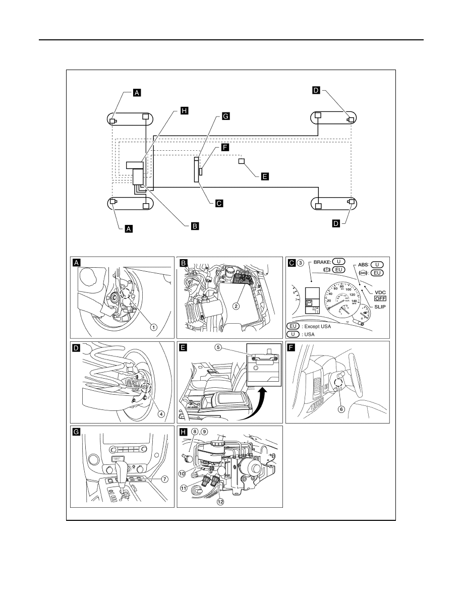
Component Parts Location
INFOID:0000000005147948
1.
Front wheel sensor LH E18
Front wheel sensor RH E117
2.
ABS actuator and electric unit (con-
trol unit) E125
3.
Combination meter M23, M24
4.
Rear wheel sensor LH C11
Rear wheel sensor RH C10
5.
Yaw rate/side/decel G sensor M108 6.
Steering angle sensor M17
AWFIA0572GB
Нет комментариевНе стесняйтесь поделиться с нами вашим ценным мнением.
Текст