Infiniti QX56 (JA60). Manual — part 1033
WW-8
< FUNCTION DIAGNOSIS >
REAR WIPER AND WASHER SYSTEM
REAR WIPER AND WASHER SYSTEM
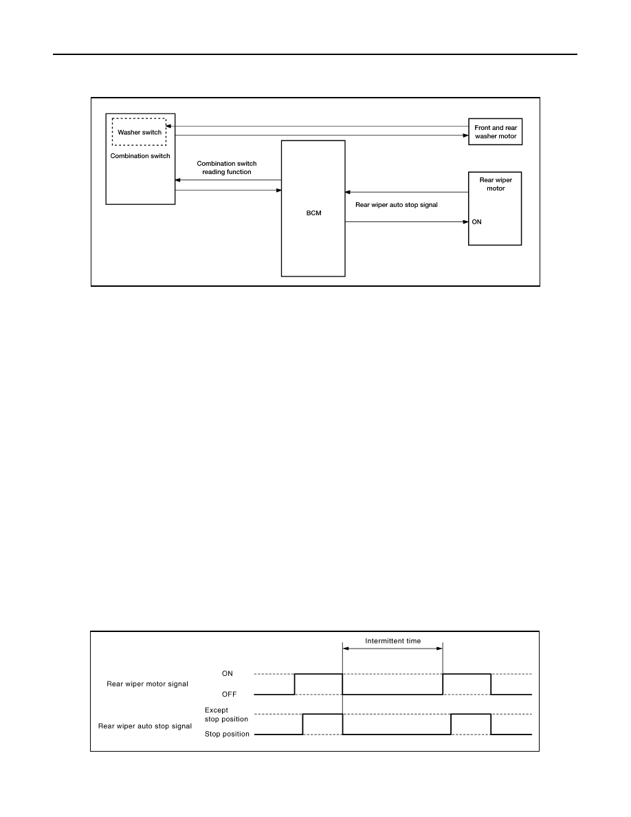
System Diagram
INFOID:0000000005146762
System Description
INFOID:0000000005146763
OUTLINE
The rear wiper is controlled by each function of BCM.
Control by BCM
• Combination switch reading function
• Rear wiper control function
REAR WIPER BASIC OPERATION
• BCM detects the combination switch condition by the combination switch reading function.
• BCM controls the rear wiper to start or stop.
REAR WIPER ON OPERATION
• BCM supplies power to the rear wiper motor according to the rear wiper ON operating condition.
Rear wiper ON operating condition
- Ignition switch ON
- Rear wiper switch ON
REAR WIPER INT OPERATION
• BCM supplies power to the rear wiper motor according to the INT operating condition.
Rear wiper INT operating condition
- Ignition switch ON
- Rear wiper switch INT
• BCM controls the rear wiper to operate once.
• BCM detects the rear wiper motor stopping position.
• BCM supplies power to the rear wiper motor after an intermittent from the stop of the rear wiper motor.
REAR WIPER AUTO STOP OPERATION
• BCM stops supplying power to the rear wiper motor when the rear wiper switch is turned OFF.
ALLIA0271GB
JPLIA0165GB

REAR WIPER AND WASHER SYSTEM
WW-9
< FUNCTION DIAGNOSIS >
C
D
E
F
G
H
I
J
K
M
A
B
WW
N
O
P
• BCM reads an auto stop signal from the rear wiper motor to detect a rear wiper motor position.
• When the rear wiper motor is at other than the stopping position, BCM continues to supply power to the rear
wiper motor until it returns to the stopping position.
NOTE:
BCM stops supplying power to the rear wiper motor when the ignition switch is turned OFF.
REAR WIPER OPERATION LINKED WITH WASHER
• BCM supplies power to the rear wiper motor according to the washer linked operating condition of rear
wiper. When the rear washer switch is turned OFF, BCM controls rear wiper to operate approximately three
times.
Washer linked operating condition of rear wiper
- Ignition switch ON
- Rear washer switch ON (0.4 second or more)
• Front and rear washer motor becomes grounded through the combination switch when the rear washer
switch is turned ON.
REAR WIPER DROP WIPE OPERATION
• BCM controls the rear wiper to operate once according to the rear wiper drop wipe operating condition.
Rear wiper drop wipe operating condition
- Ignition switch ON
- Rear wiper switch OFF
- Rear washer switch OFF
• BCM controls the rear wiper so that it operates once time approximately three seconds later after the washer
interlocking operation of the rear wiper.
REAR WIPER FAIL
−SAFE OPERATION
BCM performs the fail-safe function when the rear wiper auto stop circuit is malfunctioning. Refer to
JPLIA0166GB
WW-10
< FUNCTION DIAGNOSIS >
REAR WIPER AND WASHER SYSTEM
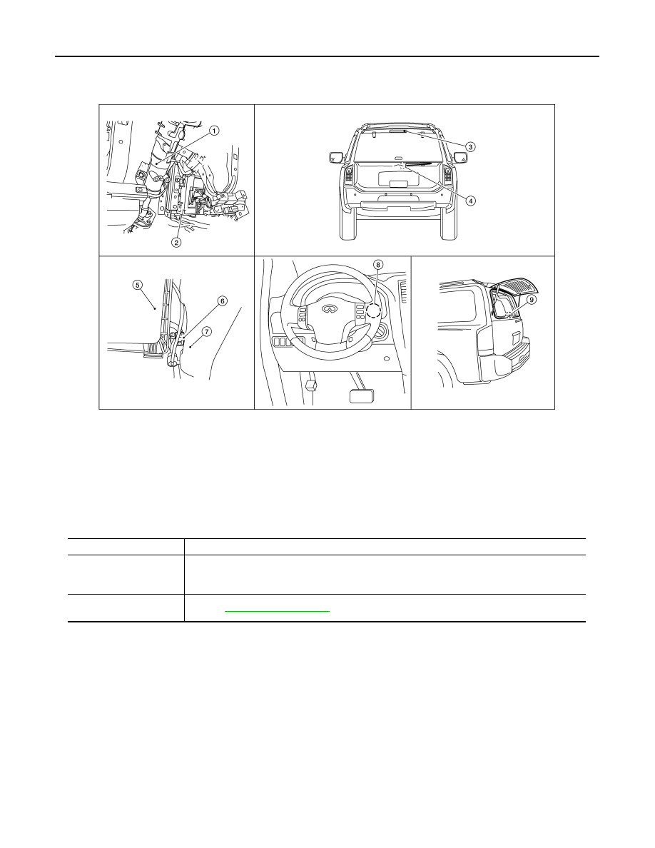
Component Parts Location
INFOID:0000000005146764
Component Description
INFOID:0000000005146765
1.
Steering column (view with instrument
panel removed)
2.
BCM M18, M19, M20
3.
Rear washer nozzle
4.
Rear wiper motor D704
5.
Air cleaner case
6.
Front and rear washer motor connector
E105
7.
Washer fluid reservoir
8.
Combination switch M28
9.
Glass hatch ajar switch D707
ALLIA0842ZZ
Part
Description
BCM
• Judges each switch status by the combination switch reading function.
• Supplies power to the rear wiper motor.
• Performs the auto stop control of the rear wiper.
Combination switch
(Wiper and washer switch)
.
DIAGNOSIS SYSTEM (BCM)
WW-11
< FUNCTION DIAGNOSIS >
C
D
E
F
G
H
I
J
K
M
A
B
WW
N
O
P
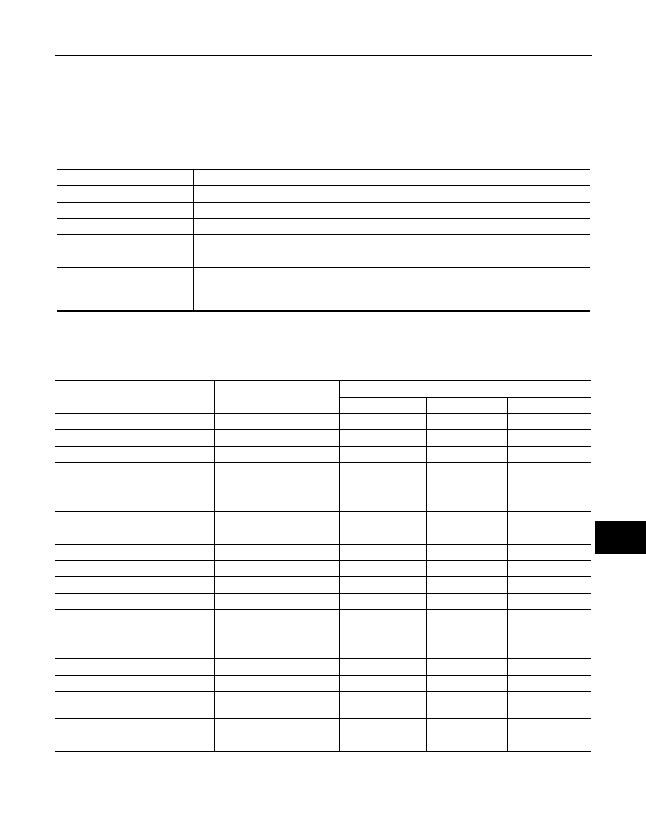
DIAGNOSIS SYSTEM (BCM)
COMMON ITEM
COMMON ITEM : CONSULT-III Function (BCM - COMMON ITEM)
INFOID:0000000005369209
APPLICATION ITEM
CONSULT-III performs the following functions via CAN communication with BCM.
SYSTEM APPLICATION
BCM can perform the following functions for each system.
NOTE:
It can perform the diagnosis modes except the following for all sub system selection items.
WIPER
Diagnosis mode
Function Description
WORK SUPPORT
Changes the setting for each system function.
SELF-DIAG RESULTS
Displays the diagnosis results judged by BCM. Refer to
CAN DIAG SUPPORT MNTR
Monitors the reception status of CAN communication viewed from BCM.
DATA MONITOR
The BCM input/output signals are displayed.
ACTIVE TEST
The signals used to activate each device are forcibly supplied from BCM.
ECU IDENTIFICATION
The BCM part number is displayed.
CONFIGURATION
• Enables to read and save the vehicle specification.
• Enables to write the vehicle specification when replacing BCM.
System
Sub system selection item
Diagnosis mode
WORK SUPPORT
DATA MONITOR
ACTIVE TEST
BCM
BCM
×
Door lock
DOOR LOCK
×
×
×
Rear window defogger
REAR DEFOGGER
×
Warning chime
BUZZER
×
×
Interior room lamp timer
INT LAMP
×
×
×
Remote keyless entry system
MULTI REMOTE ENT
×
×
Exterior lamp
HEAD LAMP
×
×
×
Wiper and washer
WIPER
×
×
×
Turn signal and hazard warning lamps FLASHER
×
×
Air conditioner
AIR CONDITONER
×
Intelligent Key system
INTELLIGENT KEY
×
Combination switch
COMB SW
×
Immobilizer
IMMU
×
×
Interior room lamp battery saver
BATTERY SAVER
×
×
×
Back door open
TRUNK
×
×
RAP (retained accessory power)
RETAINED PWR
×
×
×
Signal buffer system
SIGNAL BUFFER
×
×
TPMS (tire pressure monitoring sys-
tem)
AIR PRESSURE MONITOR
×
×
×
Vehicle security system
THEFT ALM
×
×
×
Panic alarm system
PANIC ALARM
×
Нет комментариевНе стесняйтесь поделиться с нами вашим ценным мнением.
Текст