Infiniti QX56 (JA60). Manual — part 936
TM-46
< COMPONENT DIAGNOSIS >
P0705 TRANSMISSION RANGE SWITCH A
3. Check if correct selector lever position (N/P, R or D) is displayed as selector lever is moved into each posi-
tion.
OK or NG
OK
>> GO TO 5.
NG
>> GO TO 2.
2.
CHECK TCM POWER SUPPLY AND GROUND CIRCUIT
Perform TCM power supply and ground circuit. Refer to
.
OK or NG
OK
>> GO TO 3.
NG
>> Repair or replace damaged parts.
3.
DETECT MALFUNCTIONING ITEM
Check the following items:
• A/T assembly harness connector pin terminals for damage or loose connection with harness connector.
OK or NG
OK
>> GO TO 4.
NG
>> Repair or replace damaged parts.
4.
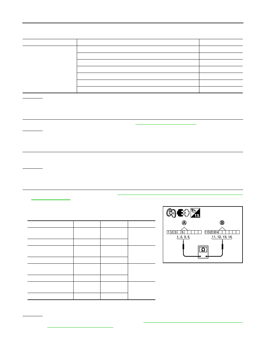
CHECK SUB-HARNESS
1. Remove control valve with TCM. Refer to
TM-172, "Control Valve with TCM and A/T Fluid Temperature
2. Disconnect transmission range switch connector and TCM connector.
3. Check continuity between transmission range switch connector
(A) terminals and TCM connector (B) terminals.
4. If OK, check harness for short to ground and short to power.
5. Reinstall any part removed.
OK or NG
OK
>> Replace the control valve with TCM. Refer to
TM-172, "Control Valve with TCM and A/T Fluid
Temperature Sensor 2 and Plug"
Item name
Condition
Display value
SLCTLVR POSI
Selector lever in “N”,“P” positions.
N/P
Selector lever in “R” position.
R
Selector lever in “D” position.
D
Selector lever in “4” position.
4
Selector lever in “3” position.
3
Selector lever in “2” position.
2
Selector lever in “1” position.
1
Item
Connector Terminal Continuity
Transmission range
switch connector
F505
1
Yes
TCM connector
F503
13
Transmission range
switch connector
F505
2
Yes
TCM connector
F503
11
Transmission range
switch connector
F505
3
Yes
TCM connector
F503
12
Transmission range
switch connector
F505
5
Yes
TCM connector
F503
14
JSDIA1328GB
P0705 TRANSMISSION RANGE SWITCH A
TM-47
< COMPONENT DIAGNOSIS >
C
E
F
G
H
I
J
K
L
M
A
B
TM
N
O
P
NG
>> Replace open circuit or short to ground and short to power in harness or connectors.
5.
CHECK DTC
Perform “DTC Confirmation Procedure”.
• Refer to
TM-45, "DTC Confirmation Procedure"
OK or NG
OK
>> INSPECTION END
NG
>> GO TO 2.

TM-48
< COMPONENT DIAGNOSIS >
P0717 INPUT SPEED SENSOR A
P0717 INPUT SPEED SENSOR A
Description
INFOID:0000000005148550
The input speed sensor detects input shaft rpm (revolutions per minute). It is located on the input side of the
automatic transmission. Monitors revolution of sensor 1 and sensor 2 for non-standard conditions.
CONSULT-III Reference Value in Data Monitor Mode
INFOID:0000000005148551
On Board Diagnosis Logic
INFOID:0000000005148552
• This is an OBD-II self-diagnostic item.
• Diagnostic trouble code “P0717 INPUT SPEED SENSOR A” with CONSULT-III is detected under the follow-
ing conditions.
- When TCM does not receive the proper voltage signal from the sensor.
- When TCM detects an irregularity only at position of 4GR for input speed sensor 2.
Possible Cause
INFOID:0000000005148553
• Harness or connectors
(The sensor circuit is open or shorted.)
• Input speed sensor 1, 2
DTC Confirmation Procedure
INFOID:0000000005148554
CAUTION:
Always drive vehicle at a safe speed.
NOTE:
If “DTC Confirmation Procedure” has been previously performed, always turn ignition switch “OFF”
and wait at least 10 seconds before performing the next test.
After the repair, perform the following procedure to confirm the malfunction is eliminated.
WITH CONSULT-III
1. Turn ignition switch “ON”. (Do not start engine.)
2. Select “DATA MONITOR” mode for “TRANSMISSION” with CONSULT-III.
3. Start engine and maintain the following conditions for at least 5 consecutive seconds.
VHCL/S SE-A/T: 40 km/h (25 MPH) or more
ENGINE SPEED: 1,500 rpm or more
ACCELE POSI: 0.5/8 or more
SLCT LVR POSI: “D” position
GEAR (Input speed sensor 1): 4th or 5th position
GEAR (Input speed sensor 2): All position
Driving location: Driving the vehicle uphill (increased engine load) will help maintain the driving
conditions required for this test.
4. If DTC is detected, go to
WITH GST
Follow the procedure “With CONSULT-III”.
Diagnosis Procedure
INFOID:0000000005148555
1.
CHECK INPUT SIGNAL
With CONSULT-III
1. Start engine.
2. Select “ECU INPUT SIGNALS” in “DATA MONITOR” mode for “TRANSMISSION” with CONSULT-III.
3. Vehicle start and read out the value of “INPUT SPEED”.
Item name
Condition
Display value (rpm)
INPUT SPEED
During driving (lock-up ON)
Approximately matches the engine speed.

P0717 INPUT SPEED SENSOR A
TM-49
< COMPONENT DIAGNOSIS >
C
E
F
G
H
I
J
K
L
M
A
B
TM
N
O
P
OK or NG
OK
>> GO TO 4.
NG
>> GO TO 2.
2.
CHECK TCM POWER SUPPLY AND GROUND CIRCUIT
Check TCM power supply and ground circuit. Refer to
OK or NG
OK
>> GO TO 3.
NG
>> Repair or replace damaged parts.
3.
DETECT MALFUNCTIONING ITEM
Check the following items:
• The A/T assembly harness connector pin terminals for damage or loose connection with harness connector.
OK or NG
OK
>> Replace the control valve with TCM. Refer to
TM-172, "Control Valve with TCM and A/T Fluid
Temperature Sensor 2 and Plug"
.
NG
>> Repair or replace damaged parts.
4.
CHECK DTC
Perform “DTC Confirmation Procedure”.
• Refer to
TM-48, "DTC Confirmation Procedure"
OK or NG
OK
>> INSPECTION END
NG
>> GO TO 2.
Item name
Condition
Display value (rpm)
INPUT SPEED
During driving (lock-up ON)
Approximately matches the engine speed.
Нет комментариевНе стесняйтесь поделиться с нами вашим ценным мнением.
Текст