Infiniti QX56 (JA60). Manual — part 14
POWER SUPPLY AND GROUND CIRCUIT
ADP-47
< COMPONENT DIAGNOSIS >
C
D
E
F
G
H
I
K
L
M
A
B
ADP
N
O
P
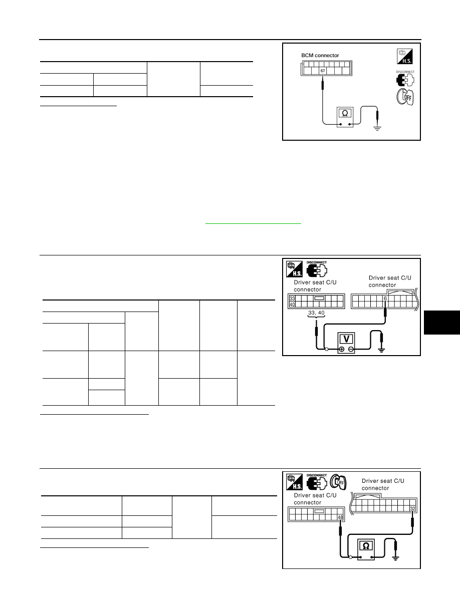
Check continuity between BCM harness connector and ground.
Does continuity exist?
YES
>> Inspection End.
NO
>> Repair or replace harness.
DRIVER SEAT CONTROL UNIT
DRIVER SEAT CONTROL UNIT : Diagnosis Procedure
INFOID:0000000005147478
NOTE:
Do not disconnect the battery negative terminal and the driver seat control unit connector until DTC is con-
firmed with CONSULT-III.
Regarding Wiring Diagram information, refer to
1.
CHECK POWER SUPPLY CIRCUIT
1. Turn ignition switch OFF.
2. Disconeect driver seat control unit.
3. Check voltage between driver seat control unit harness connec-
tor and ground.
Is the inspection result normal?
YES
>> GO TO 2
NO
>> Check the following.
• Repair or replace harness between driver seat control unit and fuse block (J/B).
• Circuit breaker.
2.
CHECK GROUND CIRCUIT
Check continuity between the driver seat control unit harness con-
nector and ground.
Is the inspection result normal?
YES
>> Driver seat control unit power supply and ground circuit
are OK.
BCM
Ground
Continuity
Connector
Terminal
M20
67
Yes
LIIA0915E
Terminals
Power
source
Condition
Voltage (V)
(Approx.)
(+)
(–)
Driver seat
control unit
connector
Terminal
B202
6
Ground
START
power sup-
ply
Ignition
switch
START
Battery
voltage
B203
33
Battery
power sup-
ply
Ignition
switch
OFF
40
LIIA1897E
Driver seat control unit
connector
Terminal
Ground
Continuity
B202
32
Yes
B203
48
PIIA4542E
ADP-48
< COMPONENT DIAGNOSIS >
POWER SUPPLY AND GROUND CIRCUIT
NO
>> Repair or replace harness.
DRIVER SEAT CONTROL UNIT : Special Repair Requirement
INFOID:0000000005147479
1.
PERFORM ADDITIONAL SERVICE
Perform additional service when removing battery negative terminal.
>> Refer to Owner’s Manual.
AUTOMATIC DRIVE POSITIONER CONTROL UNIT
AUTOMATIC DRIVE POSITIONER CONTROL UNIT : Diagnosis Procedure
INFOID:0000000005147480
NOTE:
Do not disconnect the battery negative terminal and the driver seat control unit connector until DTC is con-
firmed with CONSULT-III.
Regarding Wiring Diagram information, refer to
1.
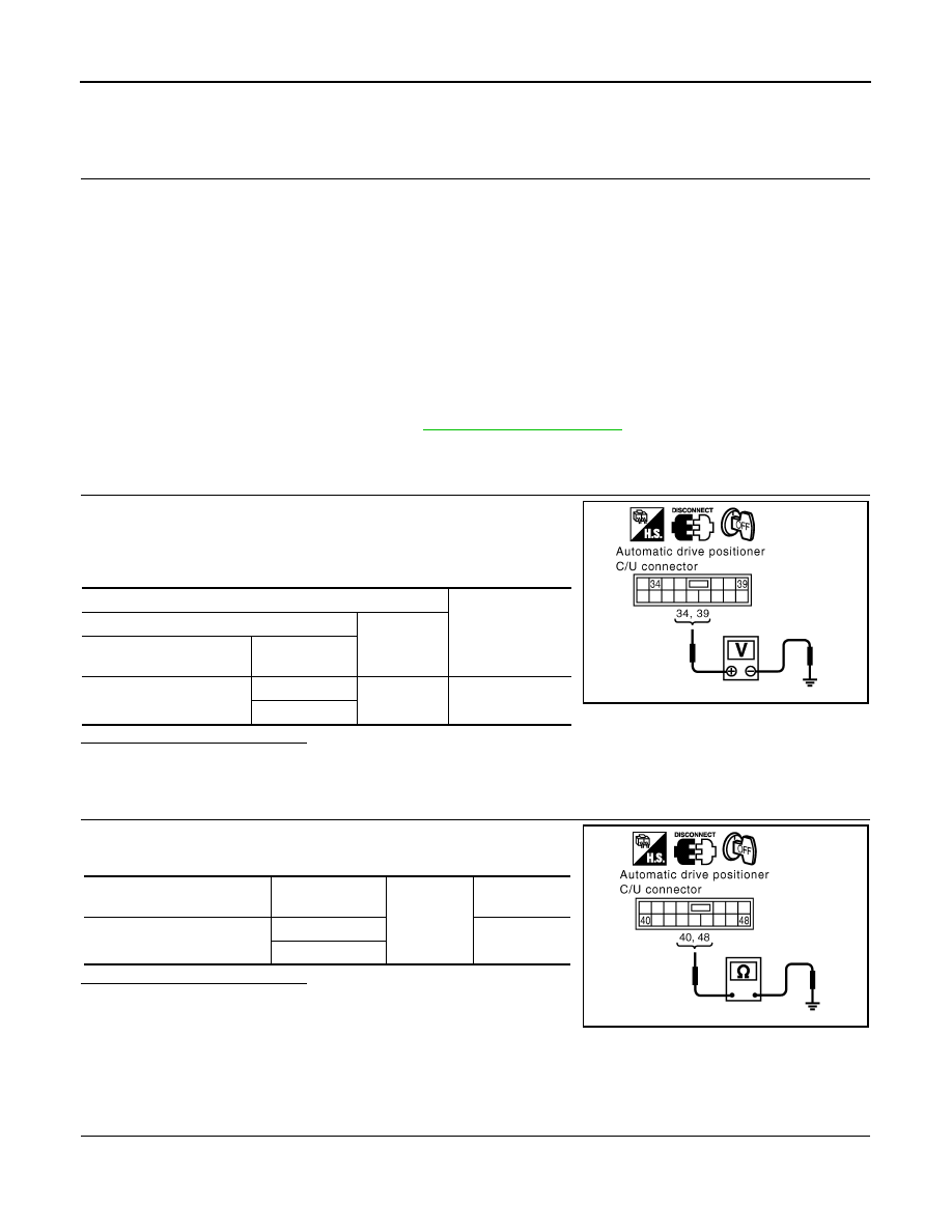
CHECK POWER SUPPLY CIRCUIT
1. Turn ignition switch OFF.
2. Disconnect automatic drive positioner control unit.
3. Check voltage between automatic drive positioner control unit
harness connector and ground.
Is the inspection result normal?
YES
>> GO TO 2
NO
>> Repair or replace harness.
2.
CHECK GROUND CIRCUIT
Check continuity between the automatic drive positioner control unit
harness connector and ground.
Is the inspection result normal?
YES
>> Automatic drive positioner control unit power supply and
ground circuit are OK.
NO
>> Repair or replace harness.
AUTOMATIC DRIVE POSITIONER CONTROL UNIT : Special Repair Requirement
INFOID:0000000005147481
1.
PERFORM ADDITIONAL SERVICE
Perform additional service when removing battery negative terminal.
Terminals
Voltage (V)
(Approx.)
(+)
(–)
Automatic drive positioner
control unit connector
Terminal
M34
34
Ground
Battery voltage
39
PIIA4543E
Automatic drive positioner
control unit connector
Terminal
Ground
Continuity
M34
40
Yes
48
PIIA4544E
POWER SUPPLY AND GROUND CIRCUIT
ADP-49
< COMPONENT DIAGNOSIS >
C
D
E
F
G
H
I
K
L
M
A
B
ADP
N
O
P
>> Refer to Owner’s Manual.
ADP-50
< COMPONENT DIAGNOSIS >
SLIDING SWITCH
SLIDING SWITCH
Description
INFOID:0000000005147482
Sliding switch is equipped to the power seat switch LH on the seat cushion trim cover. The operation signal is
input to the driver seat control unit when the sliding switch is operated.
Component Function Check
INFOID:0000000005147483
1.
CHECK FUNCTION
1. Select “SLIDE SW-FR”, “SLIDE SW-RR” in “Data monitor” mode with CONSULT-III.
2. Check sliding switch signal under the following conditions.
Is the indication normal?
YES
>> Inspection End.
NO
>> Perform diagnosis procedure. Refer to
Diagnosis Procedure
INFOID:0000000005147484
Regarding Wiring Diagram information, refer to
1.
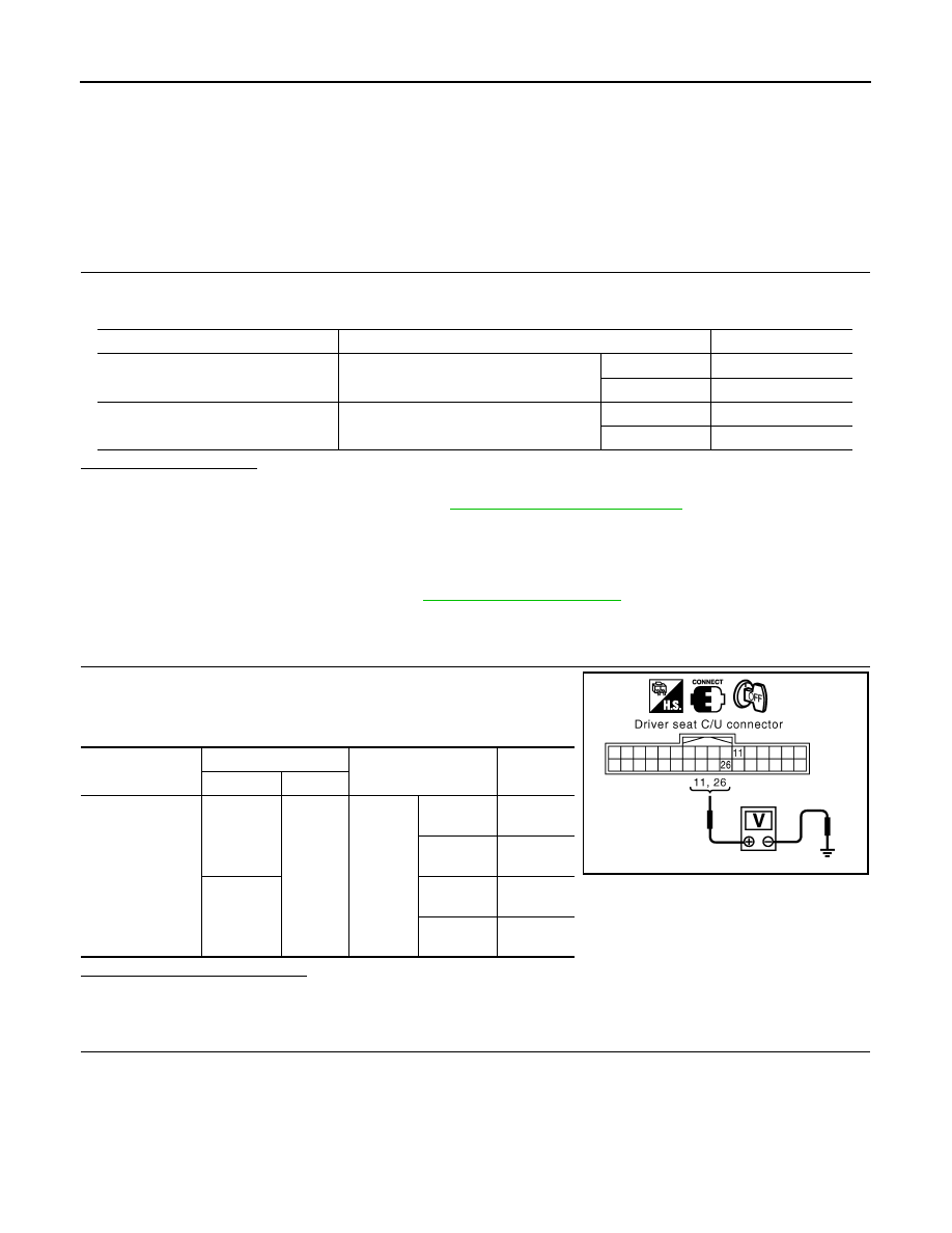
CHECK SLIDING SWITCH SIGNAL
1. Turn ignition switch OFF.
2. Check voltage between driver seat control unit harness connec-
tor and ground.
Is the inspection result normal?
YES
>> GO TO 5
NO
>> GO TO 2
2.
CHECK SLIDING SWITCH CIRCUIT
Monitor item
Condition
Status
SLIDE SW-FR
Sliding switch (forward)
Operate
ON
Release
OFF
SLIDE SW-RR
Sliding switch (backward)
Operate
ON
Release
OFF
Driver seat control
unit connector
Terminals
Condition
Voltage (V)
(Approx.)
(+)
(–)
B202
11
Ground
Sliding
switch
Operate
(backward)
0
Release
Battery
voltage
26
Operate
(forward)
0
Release
Battery
voltage
PIIA4577E
Нет комментариевНе стесняйтесь поделиться с нами вашим ценным мнением.
Текст