Infiniti QX56 (JA60). Manual — part 298
HEAVY TIGHT-CORNER BRAKING SYMPTOM OCCURS
DLN-115
< SYMPTOM DIAGNOSIS >
[ATX14B]
C
E
F
G
H
I
J
K
L
M
A
B
DLN
N
O
P
Are the inspection results normal?
YES
>> Inspection End.
NO
>> Repair or replace damaged parts.
DLN-116
< SYMPTOM DIAGNOSIS >
[ATX14B]
ATP SWITCH
ATP SWITCH
Description
INFOID:0000000005148873
The ATP indicator is ON when the transfer case is not in neutral.
Diagnosis Procedure
INFOID:0000000005148874
Regarding Wiring Diagram information, refer to
DLN-89, "Wiring Diagram - ALL-MODE 4WD SYSTEM -"
.
1.
CHECK ATP SWITCH SIGNAL
With CONSULT-III
1. Start engine.
2. Select DATA MONITOR mode for ALL MODE AWD/4WD with CONSULT-III.
3. Read out the value of ATP SWITCH.
Without CONSULT-III
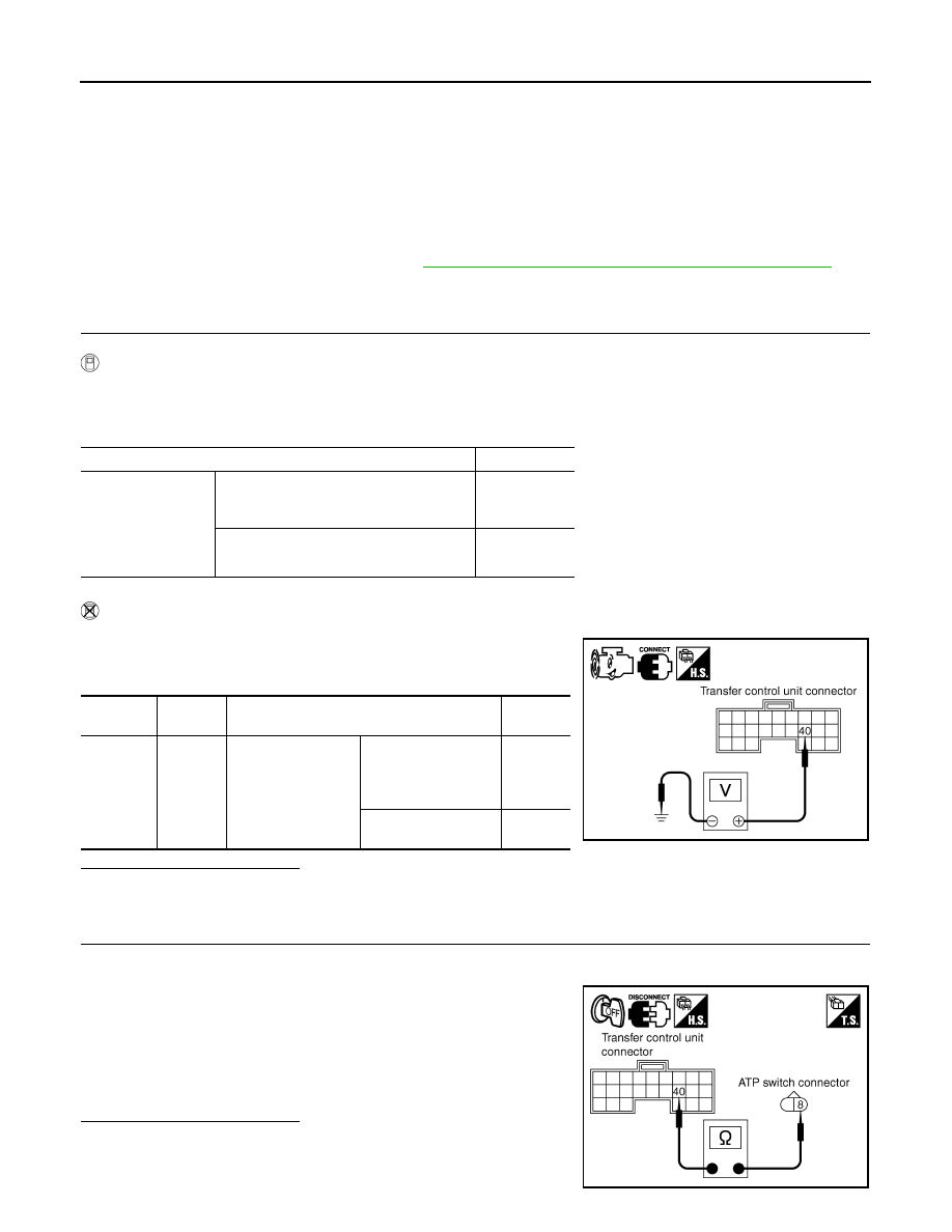
1. Start engine.
2. Check voltage between transfer control unit harness connector
terminal and ground.
Are inspection results normal?
YES
>> GO TO 5.
NO
>> GO TO 2.
2.
CHECK HARNESS BETWEEN TRANSFER CONTROL UNIT AND ATP SWITCH
1. Turn ignition switch OFF. (Stay for at least 5 seconds.)
2. Disconnect transfer control unit harness connector and the ATP switch harness connector.
3. Check continuity between transfer control unit harness connec-
tor E143 terminal 40 and ATP switch harness connector F55 ter-
minal 8.
Also check harness for short to ground and short to power.
Are inspection results normal?
YES
>> GO TO 3.
NO
>> Repair or replace damaged parts.
Condition
Display value
• Vehicle stopped
• Engine running
• A/T selector lever
N
• Brake pedal de-
pressed
4WD shift switch
: 4H to 4LO or 4LO to 4H
(While actuator motor is operating.)
ON
Except the above
OFF
Connector
Terminal
Condition
Voltage
(Approx.)
E143
40 -
Ground
• Vehicle stopped
• Engine running
• A/T selector lever
N
• Brake pedal de-
pressed
4WD shift switch: 4H
to 4LO or 4LO to 4H
(While actuator motor
is operating.)
0V
Except the above
Battery
voltage
SDIA2755E
Continuity should exist.
SDIA2756E
ATP SWITCH
DLN-117
< SYMPTOM DIAGNOSIS >
[ATX14B]
C
E
F
G
H
I
J
K
L
M
A
B
DLN
N
O
P
3.
CHECK GROUND CIRCUIT
1. Turn ignition switch OFF. (Stay for at least 5 seconds.)
2. Disconnect ATP switch harness connector.
3. Check continuity between ATP switch harness connector F55
terminal 9 and ground.
Also check harness for short to ground and short to power.
Are inspection results normal?
YES
>> GO TO 4.
NO
>> Repair open circuit or short to ground or short to power
in harness or connectors.
4.
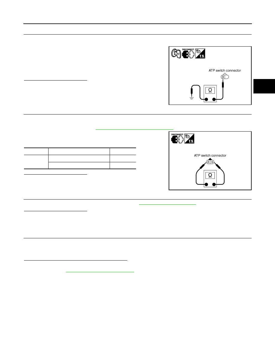
CHECK ATP SWITCH
1. Turn ignition switch OFF. (Stay for at least 5 seconds.)
2. Disconnect ATP switch harness connector.
3. Remove ATP switch. Refer to
DLN-16, "Component Parts Location"
4. Push and release ATP switch and check continuity between ATP
switch terminals 8 and 9.
Are inspection results normal?
YES
>> GO TO 5.
NO
>> Replace ATP switch.
5.
CHECK TRANSFER CONTROL UNIT
Check transfer control unit input/output signal. Refer to
Are inspection results normal?
YES
>> GO TO 6.
NO
>> Check transfer control unit pin terminals for damage or loose connection with harness connector.
If any items are damaged, repair or replace damaged parts.
6.
CHECK ATP WARNING LAMP
1. Turn ignition switch ON. (Do not start engine.)
2. Move A/T selector lever to P position.
3. Set 4WD shift switch from 4H to 4LO or 4LO to 4H.
Does ATP warning lamp turn ON while switching?
YES
>> Inspection End.
NO
>> GO TO
DLN-109, "Diagnosis Procedure"
.
Continuity should exist.
SDIA2394E
Terminal
Condition
Continuity
8 - 9
Push ATP switch
Yes
Release ATP switch
No
SDIA2757E

DLN-118
< SYMPTOM DIAGNOSIS >
[ATX14B]
4WD SYSTEM DOES NOT OPERATE
4WD SYSTEM DOES NOT OPERATE
Description
INFOID:0000000005148875
The vehicle can not be put into 4WD mode. (Possible hydraulic malfunction)
Diagnosis Procedure
INFOID:0000000005148876
1.
CHECK SYSTEM FOR 4WD SHIFT SWITCH
Perform trouble diagnosis for 4WD shift switch system. Refer to
Are the inspection results normal?
YES
>> GO TO 2.
NO
>> Repair or replace damaged parts.
2.
CHECK SYSTEM FOR CLUTCH PRESSURE SWITCH
Perform trouble diagnosis for clutch pressure switch system. Refer to
.
Are the inspection results normal?
YES
>> GO TO 3.
NO
>> Repair or replace damaged parts.
3.
SYMPTOM CHECK
Check again.
Are the inspection results normal?
YES
>> Inspection End.
NO
>> GO TO 4.
4.
CHECK TRANSFER CONTROL UNIT
Check transfer control unit input/output signal. Refer to
.
Are the inspection results normal?
YES
>> GO TO 5.
NO
>> Check transfer control unit pin terminals for damage or loose connection with harness connector.
If any items are damaged, repair or replace damaged parts.
5.
CHECK TRANSFER INNER PARTS
1. Disassemble transfer assembly. Refer to
DLN-142, "Disassembly and Assembly"
2. Check transfer inner parts.
Are the inspection results normal?
YES
>> Inspection End.
NO
>> Repair or replace damaged parts.
Нет комментариевНе стесняйтесь поделиться с нами вашим ценным мнением.
Текст