Infiniti QX56 (JA60). Manual — part 22
FRONT DOOR SWITCH (DRIVER SIDE)
ADP-79
< COMPONENT DIAGNOSIS >
C
D
E
F
G
H
I
K
L
M
A
B
ADP
N
O
P
FRONT DOOR SWITCH (DRIVER SIDE)
Description
INFOID:0000000005147522
Detects front door LH open/close condition.
Component Function Check
INFOID:0000000005147523
1.
CHECK FUNCTION
1. Select “DOOR SW-DR” in “Data monitor” mode with CONSULT-III.
2. Check the front door switch LH signal under the following conditions.
Is the inspection result normal?
YES
>> Inspection End.
NO
>> Perform diagnosis procedure. Refer to
.
Diagnosis Procedure
INFOID:0000000005147524
Regarding Wiring Diagram information, refer to
1.
CHECK FRONT DOOR SWITCH LH CIRCUIT
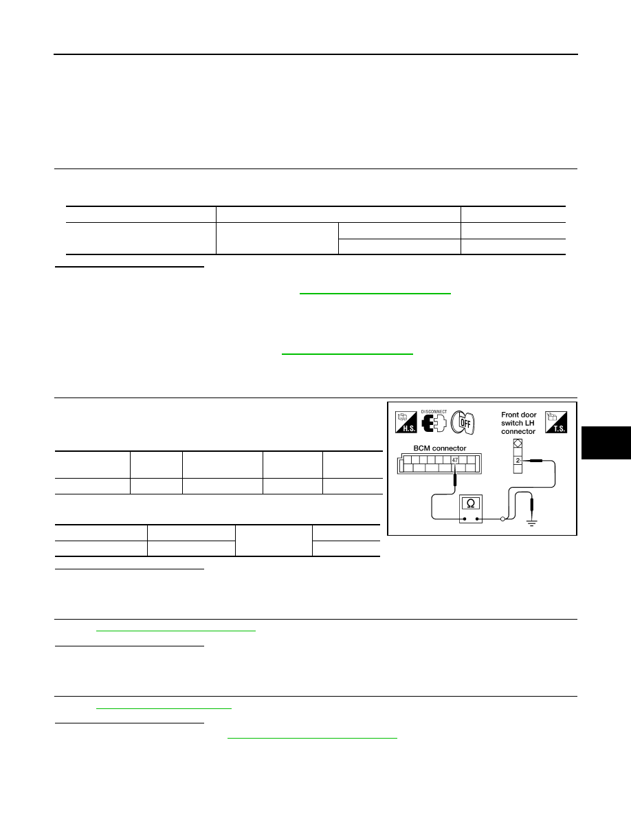
1. Disconnect BCM and front door switch LH.
2. Check continuity between BCM connector and front door switch
LH connector.
3. Check continuity between BCM connector and ground.
Is the inspection result normal?
YES
>> GO TO 2
NO
>> Repair or replace harness.
2.
CHECK FRONT DOOR SWITCH LH
ADP-80, "Component Inspection"
.
Is the inspection result normal?
YES
>> GO TO 3
NO
>> Replace front door switch LH.
3.
CHECK INTERMITTENT INCIDENT
GI-38, "Intermittent Incident"
.
Is the inspection result normal?
YES
>> Replace BCM. Refer to
BCS-59, "Removal and Installation"
NO
>> Repair or replace the malfunctioning part.
Monitor item
Condition
Status
DOOR SW-DR
Front door switch LH
Open
ON
Close
OFF
BCM connector
Terminal
Front door switch
LH connector
Terminal
Continuity
M19
47
B8
2
Yes
BCM connector
Terminal
Ground
Continuity
M19
47
No
LIIA1027E
ADP-80
< COMPONENT DIAGNOSIS >
FRONT DOOR SWITCH (DRIVER SIDE)
Component Inspection
INFOID:0000000005147525
1.
CHECK FRONT DOOR SWITCH LH
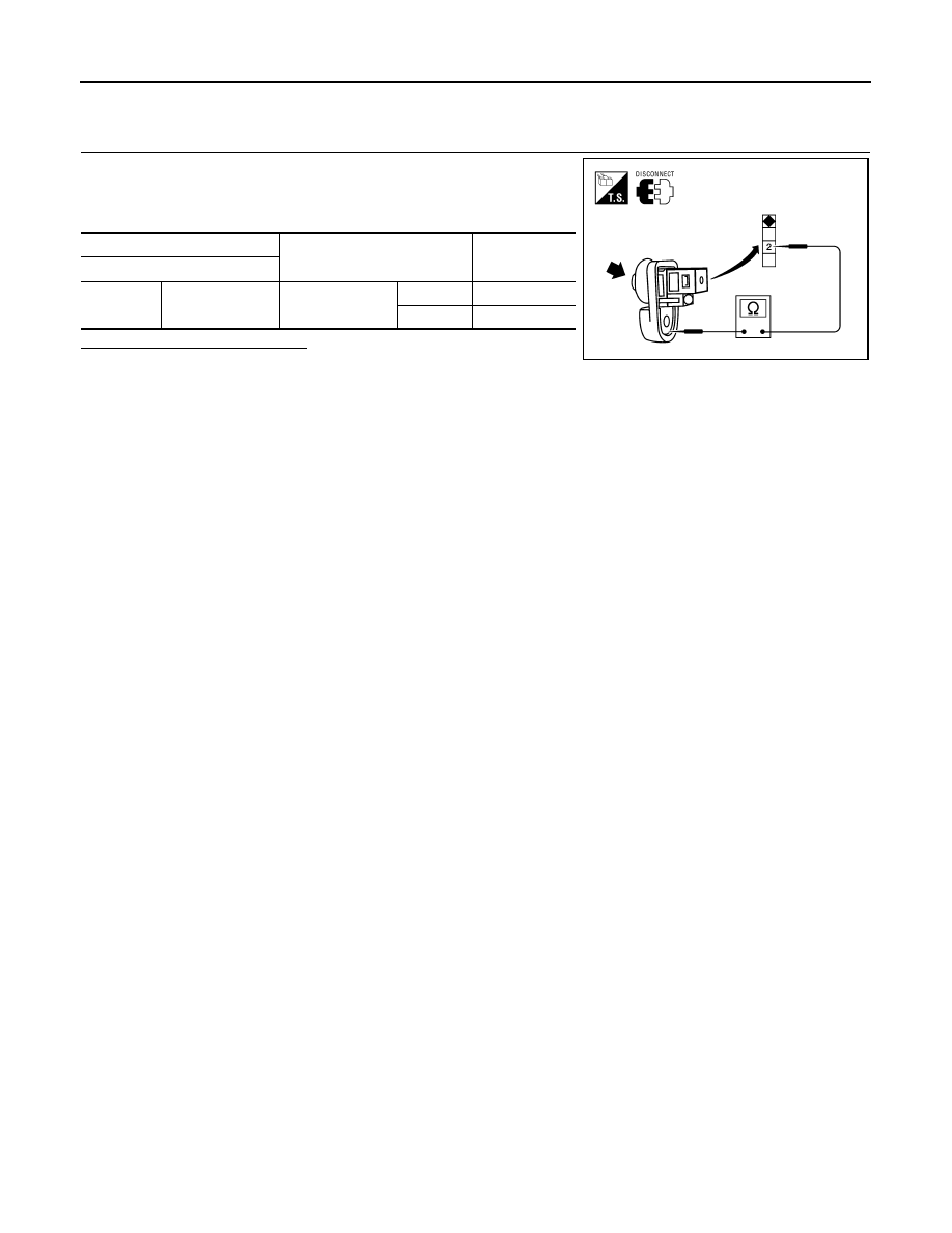
1. Turn ignition switch OFF.
2. Disconnect front door switch LH.
3. Check continuity between front door switch LH terminals.
Is the inspection result normal?
YES
>> Inspection End.
NO
>> Replace front door switch LH.
Terminal
Condition
Continuity
Front door switch LH
2
Ground part of
door switch
Front door switch
LH
Pushed
No
Released
Yes
LIIA2377E
SLIDING SENSOR
ADP-81
< COMPONENT DIAGNOSIS >
C
D
E
F
G
H
I
K
L
M
A
B
ADP
N
O
P
SLIDING SENSOR
Description
INFOID:0000000005147526
• The sliding sensor is installed to the power seat frame assembly.
• The pulse signal is input to the driver seat control unit when sliding is performed.
• The driver seat control unit counts the pulse and calculates the sliding amount of the seat.
Component Function Check
INFOID:0000000005147527
1.
CHECK FUNCTION
1. Select “SLIDE PULSE” in “Data monitor” mode with CONSULT-III.
2. Check sliding sensor signal under the following conditions.
Is the indication normal?
YES
>> Inspection End.
NO
>> Perform diagnosis procedure. Refer to
Diagnosis Procedure
INFOID:0000000005147528
Regarding Wiring Diagram information, refer to
1.
CHECK SLIDING SENSOR SIGNAL
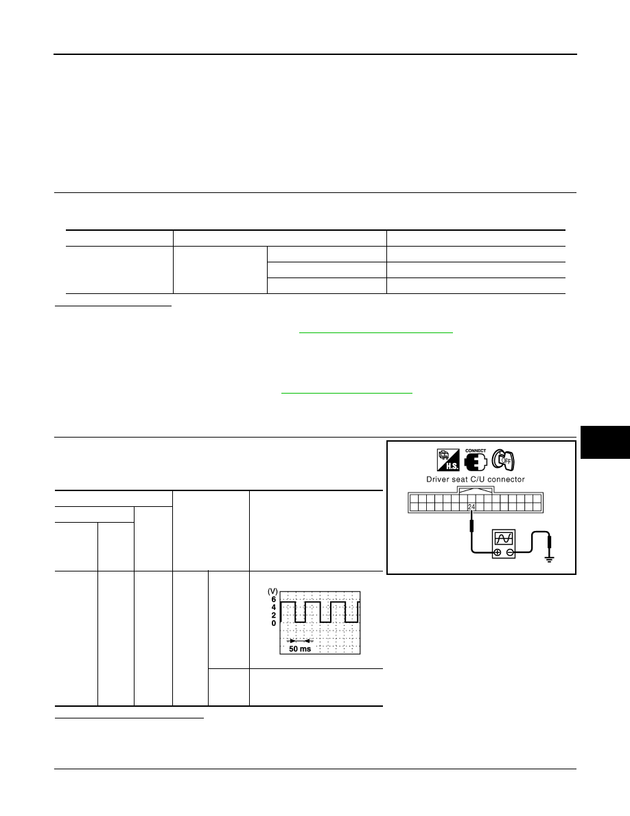
1. Turn ignition switch OFF.
2. Read voltage signal between driver seat control unit harness
connector and ground with osiloscope.
Is the inspection result normal?
YES
>> GO TO 4
NO
>> GO TO 2
2.
CHECK SLIDING SENSOR CIRCUITS
Monitor item
Condition
Valve
SLIDE PULSE
Seat sliding
Operate (forward)
Change (increase)
Operate (backward)
Change (decrease)
Release
No change
Terminals
Condition
Voltage signal
(+)
(–)
Driver’s
seat
control
unit
Termi-
nal
B202
24
Ground
Seat
sliding
Operate
Other
than
above
0 or 5
PIIA4556E
PIIA3277E
ADP-82
< COMPONENT DIAGNOSIS >
SLIDING SENSOR
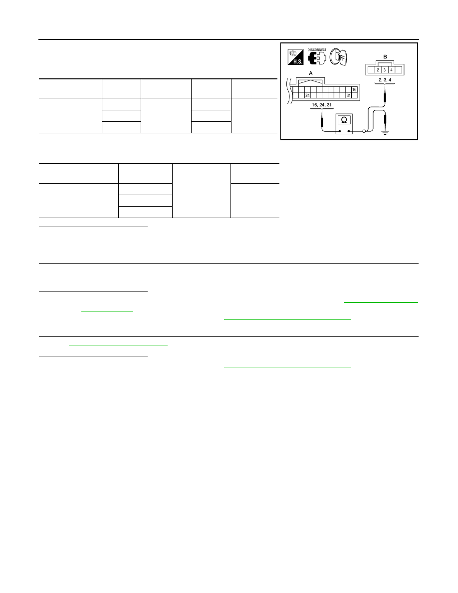
1. Disconnect driver seat control unit and sliding motor LH.
2. Check continuity between driver seat control unit harness con-
nector and sliding motor LH harness connector.
3. Check continuity between driver seat control unit harness con-
nector and ground.
Is the inspection result normal?
YES
>> GO TO 3
NO
>> Repair or replace harness.
3.
CHECK SEAT OPERATION
1. Connect driver seat control unit and sliding motor LH.
2. Check seat operation (except sliding operation) with memory function.
Is the inspection result normal?
YES
>> Replace sliding motor LH. (Built in power seat frame assembly). Refer to
.
NO
>> Replace driver seat control unit. Refer to
ADP-174, "Removal and Installation"
4.
CHECK INTERMITTENT INCIDENT
GI-38, "Intermittent Incident"
Is the inspection result normal?
YES
>> Replace driver seat control unit. Refer to
ADP-174, "Removal and Installation"
NO
>> Repair or replace the malfunctioning part.
Driver seat control
unit connector
Terminal
Sliding motor
LH connector
Terminal
Continuity
B202 (A)
16
B204 (B)
3
Yes
24
4
31
2
Driver seat control unit
connector
Terminal
Ground
Continuity
B202 (A)
16
No
24
31
ALJIA0317ZZ
Нет комментариевНе стесняйтесь поделиться с нами вашим ценным мнением.
Текст