Infiniti QX56 (JA60). Manual — part 415
EC-312
< COMPONENT DIAGNOSIS >
[VK56DE]
P1550 BATTERY CURRENT SENSOR
P1550 BATTERY CURRENT SENSOR
Component Description
INFOID:0000000005149366
The power generation voltage variable control enables fuel con-
sumption to be decreased by reducing the engine load which is
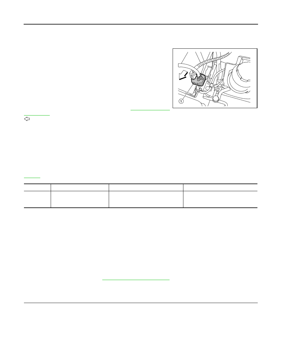
caused by the power generation of the generator. The battery cur-
rent sensor (1) is installed to the battery cable at the negative termi-
nal. The sensor measures the charging/discharging current of the
battery. Based on the sensor signal, ECM judges whether or not the
power generation voltage variable control is performed. When per-
forming the power generation voltage variable control, ECM calcu-
lates the target power generation voltage based on the sensor
signal. And ECM sends the calculated value as the power genera-
tion command value to IPDM E/R. For the details of the power gen-
eration voltage variable control, refer to
.
: Vehicle front
CAUTION:
Do not connect the electrical component or the ground wire directly to the battery terminal. The con-
nection causes the malfunction of the power generation voltage variable control, and then the battery
discharge may occur.
On Board Diagnosis Logic
INFOID:0000000005149367
The MIL will not light up for this self-diagnosis.
NOTE:
If DTC P1550 is displayed with DTC P0643, first perform the trouble diagnosis for DTC P0643. Refer to
.
DTC Confirmation Procedure
INFOID:0000000005149368
If DTC Confirmation Procedure has been previously conducted, always perform the following procedure
before conducting the next step.
1. Turn ignition switch OFF and wait at least 10 seconds.
2. Turn ignition switch ON.
3. Turn ignition switch OFF and wait at least 10 seconds.
TESTING CONDITION:
Before performing the following procedure, confirm that battery voltage is more than 8 V at idle.
1. Start engine and wait at least 10 seconds.
2. Check 1st trip DTC.
3. If 1st trip DTC is detected, go to
Diagnosis Procedure
INFOID:0000000005149369
1.
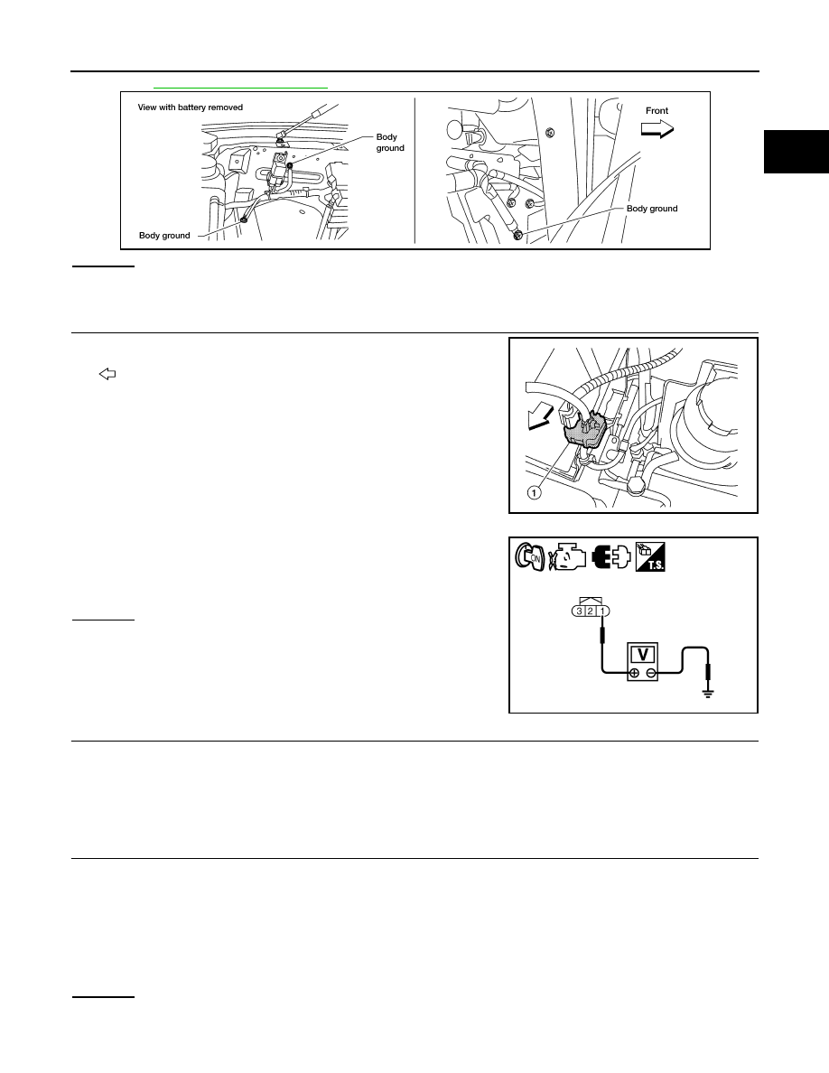
CHECK GROUND CONNECTIONS
1. Turn ignition switch OFF.
2. Loosen and retighten ground screws on the body.
BBIA0744E
DTC No.
Trouble diagnosis name
DTC detecting condition
Possible cause
P1550
1550
Battery current sensor circuit
range/performance
The output voltage of the battery current
sensor remains within the specified
range while engine is running.
• Harness or connectors
(The sensor circuit is open or shorted.)
• Battery current sensor
P1550 BATTERY CURRENT SENSOR
EC-313
< COMPONENT DIAGNOSIS >
[VK56DE]
C
D
E
F
G
H
I
J
K
L
M
A
EC
N
P
O
OK or NG
OK
>> GO TO 2.
NG
>> Repair or replace ground connections.
2.
CHECK BATTERY CURRENT SENSOR POWER SUPPLY CIRCUIT
1. Disconnect battery current sensor (1) harness connector.
2. Turn ignition switch ON.
: Vehicle front
3. Check voltage between battery current sensor terminal 1 and
ground with CONSULT-III or tester.
OK or NG
OK
>> GO TO 4.
NG
>> GO TO 3.
3.
DETECT MALFUNCTIONING PART
Check the following.
• Harness connectors E5, F14
• Harness for open or short between battery current sensor and ECM
>> Repair open circuit or short to ground or short to power in harness or connectors.
4.
CHECK BATTERY CURRENT SENSOR GROUND CIRCUIT FOR OPEN AND SHORT
1. Turn ignition switch OFF.
2. Disconnect ECM harness connector.
3. Check harness continuity between battery current sensor terminal 2 and ECM terminal 67.
Refer to Wiring Diagram.
4. Also check harness for short to ground and short to power.
OK or NG
OK
>> GO TO 6.
NG
>> GO TO 5.
BBIA0354E
BBIA0744E
Voltage: Approximately 5 V
PBIA9891J
Continuity should exist.
EC-314
< COMPONENT DIAGNOSIS >
[VK56DE]
P1550 BATTERY CURRENT SENSOR
5.
DETECT MALFUNCTIONING PART
Check the following.
• Harness connectors E5, F14
• Harness for open or short between battery current sensor and ECM
>> Repair open circuit or short to ground or short to power in harness or connectors.
6.
CHECK BATTERY CURRENT SENSOR INPUT SIGNAL CIRCUIT FOR OPEN AND SHORT
1. Check harness continuity between battery current sensor terminal 3 and ECM terminal 71.
Refer to Wiring Diagram.
2. Also check harness for short to ground and short to power.
OK or NG
OK
>> GO TO 8.
NG
>> GO TO 7.
7.
DETECT MALFUNCTIONING PART
Check the following.
• Harness connectors E2, F32
• Harness for open or short between battery current sensor and ECM
>> Repair open circuit or short to ground or short to power in harness or connectors.
8.
CHECK BATTERY CURRENT SENSOR
EC-314, "Component Inspection"
OK or NG
OK
>> GO TO 9.
NG
>> Replace battery negative cable assembly.
9.
CHECK INTERMITTENT INCIDENT
GI-35, "How to Check Terminal"
and
GI-38, "Intermittent Incident"
>> INSPECTION END
Component Inspection
INFOID:0000000005149370
BATTERY CURRENT SENSOR
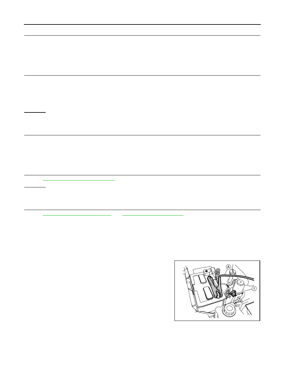
1. Reconnect harness connectors disconnected.
2. Disconnect battery negative cable (1).
3. Install jumper cable (A) between battery negative terminal and
body ground.
4. Turn ignition switch ON.
Continuity should exist.
BBIA0745E
P1550 BATTERY CURRENT SENSOR
EC-315
< COMPONENT DIAGNOSIS >
[VK56DE]
C
D
E
F
G
H
I
J
K
L
M
A
EC
N
P
O
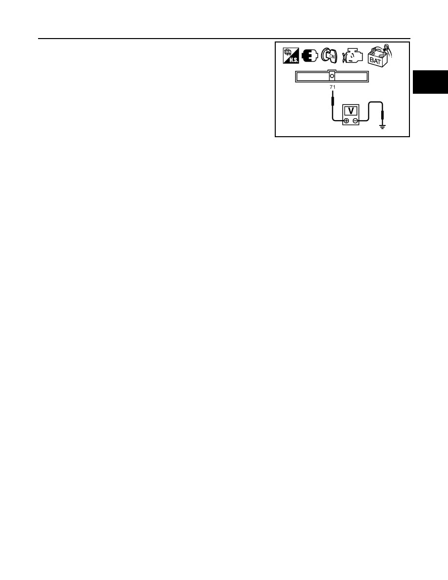
5. Check voltage between ECM terminal 71 (battery current sensor
signal) and ground.
6. If NG, replace battery negative cable assembly.
Voltage: Approximately 2.5 V
PBIB2617E
Нет комментариевНе стесняйтесь поделиться с нами вашим ценным мнением.
Текст