Infiniti QX56 (JA60). Manual — part 419
EC-328
< COMPONENT DIAGNOSIS >
[VK56DE]
P1564 ICC STEERING SWITCH
P1564 ICC STEERING SWITCH
Component Description
INFOID:0000000005149386
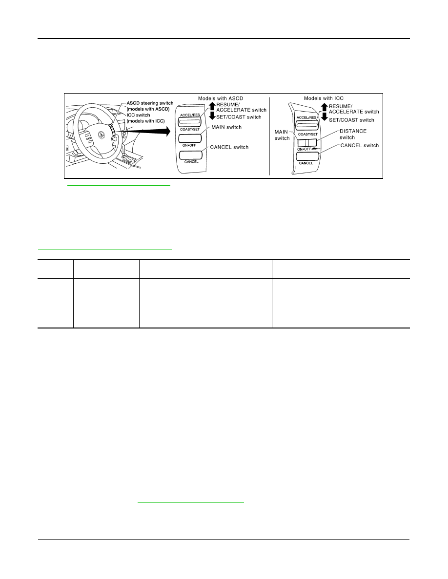
ICC steering switch has variant values of electrical resistance for each button. ECM reads voltage variation of
switch, and determines which button is operated.
for the ICC function.
On Board Diagnosis Logic
INFOID:0000000005149387
This self-diagnosis has the one trip detection logic.
The MIL will not light up for this self-diagnosis.
NOTE:
If DTC P1564 is displayed with DTC P0605, first perform the trouble diagnosis for DTC P0605. Refer to
EC-286, "On Board Diagnosis Logic"
.
DTC Confirmation Procedure
INFOID:0000000005149388
1. If DTC Confirmation Procedure has been previously conducted, always perform the following procedure
before conducting the next step.
a. Turn ignition switch OFF and wait at least 10 seconds.
b. Turn ignition switch ON.
c.
Turn ignition switch OFF and wait at least 10 seconds.
2. Turn ignition switch ON.
3. Wait at least 10 seconds.
4. Press MAIN switch for at least 10 seconds, then release it and wait at least 10 seconds.
5. Press CANCEL switch for at least 10 seconds, then release it and wait at least 10 seconds.
6. Press RESUME/ACCELERATE switch for at least 10 seconds, then release it and wait at least 10 sec-
onds.
7. Press SET/COAST switch for at least 10 seconds, then release it and wait at least 10 seconds.
8. Press DISTANCE switch for at least 10 seconds, then release it and wait at least 10 seconds.
9. Check DTC.
10. If DTC is detected, go to
.
Diagnosis Procedure
INFOID:0000000005149389
1.
CHECK GROUND CONNECTIONS
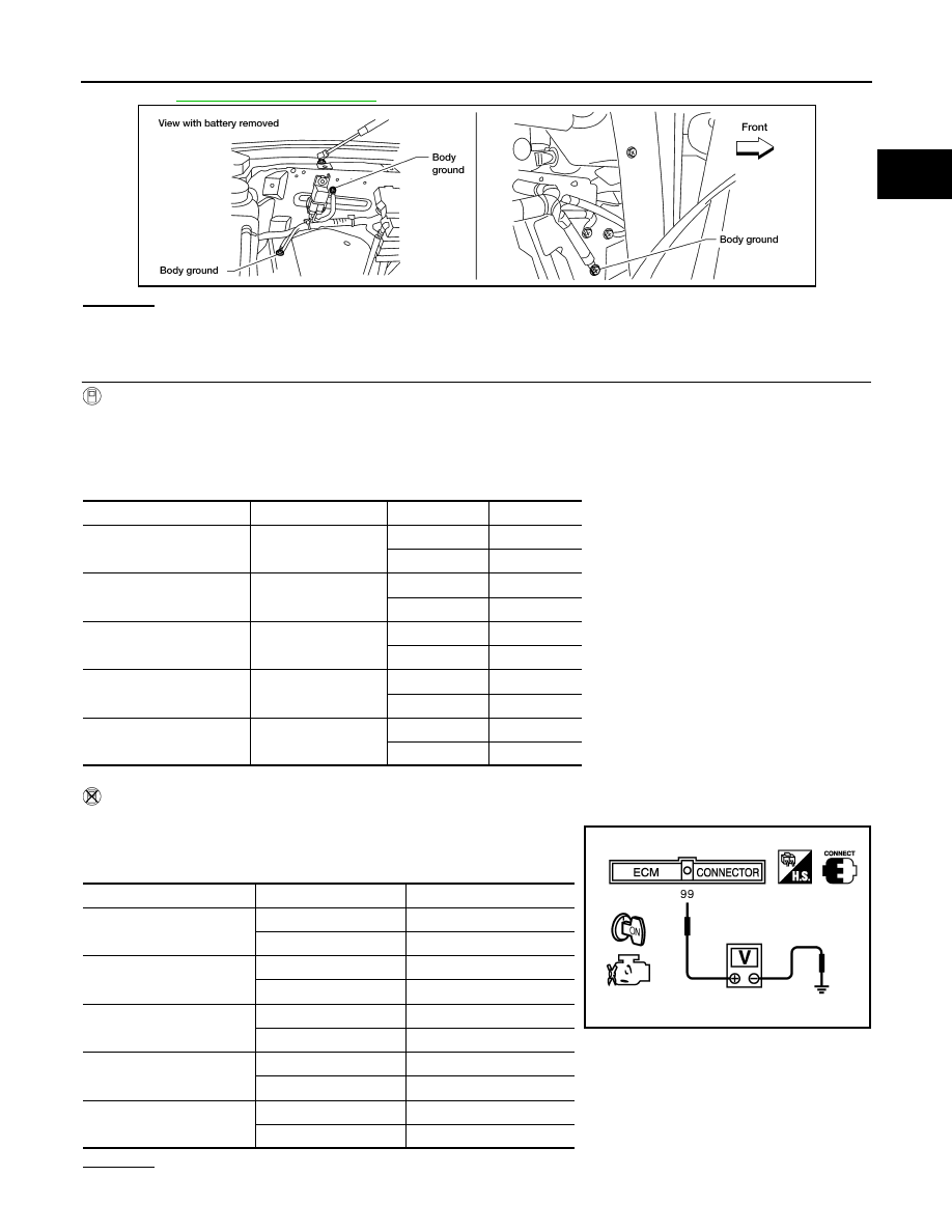
1. Turn ignition switch OFF.
2. Loosen and retighten three ground screws on the body.
PBIB2640E
DTC No.
Trouble diagnosis
name
DTC detecting condition
Possible cause
P1564
1564
ICC steering switch
• An excessively high voltage signal from the
ICC steering switch is sent to ECM.
• ECM detects that input signal from the ICC
steering switch is out of the specified range.
• ECM detects that the ICC steering switch is
stuck ON.
• Harness or connectors
(The switch circuit is open or shorted.)
• ICC steering switch
• Combination switch (spiral cable)
• ECM
P1564 ICC STEERING SWITCH
EC-329
< COMPONENT DIAGNOSIS >
[VK56DE]
C
D
E
F
G
H
I
J
K
L
M
A
EC
N
P
O
OK or NG
OK
>> GO TO 2.
NG
>> Repair or replace ground connections.
2.
CHECK ICC STEERING SWITCH CIRCUIT
With CONSULT-III
1. Turn ignition switch ON.
2. Select “MAIN SW”, “CANCEL SW”, “RESUME/ACC SW”, “SET SW” and “DIST SW” in “DATA MONITOR”
mode with CONSULT-III.
3. Check each item indication under the following conditions.
Without CONSULT-III
1. Turn ignition switch ON.
2. Check voltage between ECM terminal 99 and ground with press-
ing each button.
OK or NG
BBIA0354E
Switch
Monitor item
Condition
Indication
MAIN switch
MAIN SW
Pressed
ON
Released
OFF
CANCEL switch
CANCEL SW
Pressed
ON
Released
OFF
RESUME/ACCELERATE
switch
RESUME/ACC SW
Pressed
ON
Released
OFF
SET/COAST switch
SET SW
Pressed
ON
Released
OFF
DISTANCE switch
DIST SW
Pressed
ON
Released
OFF
Switch
Condition
Voltage [V]
MAIN switch
Pressed
Approx. 0
Released
Approx. 4.3
CANCEL switch
Pressed
Approx. 1.3
Released
Approx. 4.3
RESUME/ACCELERATE
switch
Pressed
Approx. 3.7
Released
Approx. 4.3
SET/COAST switch
Pressed
Approx. 3.0
Released
Approx. 4.3
DISTANCE switch
Pressed
Approx. 2.2
Released
Approx. 4.3
PBIB0311E

EC-330
< COMPONENT DIAGNOSIS >
[VK56DE]
P1564 ICC STEERING SWITCH
OK
>> GO TO 8.
NG
>> GO TO 3.
3.
CHECK ICC STEERING SWITCH GROUND CIRCUIT FOR OPEN AND SHORT
1. Turn ignition switch OFF.
2. Disconnect ECM harness connector.
3. Disconnect combination switch harness connector M102.
4. Check harness continuity between combination switch terminal 15 and ECM terminal 67.
Refer to Wiring Diagram.
5. Also check harness for short to ground and short to power.
OK or NG
OK
>> GO TO 5.
NG
>> GO TO 4.
4.
DETECT MALFUNCTIONING PART
Check the following.
• Harness connectors M31, E152
• Harness connectors E5, F14
• Combination switch (spiral cable)
• Harness for open and short between ECM and combination switch
>> Repair open circuit or short to ground or short to power in harness or connectors.
5.
CHECK ICC STEERING SWITCH INPUT SIGNAL CIRCUIT FOR OPEN AND SHORT
1. Check harness continuity between ECM terminal 99 and combination switch terminal 14.
Refer to Wiring Diagram.
2. Also check harness for short to ground and short to power.
OK or NG
OK
>> GO TO 7.
NG
>> GO TO 6.
6.
DETECT MALFUNCTIONING PART
Check the following.
• Harness connectors M31, E152
• Combination switch (spiral cable)
• Harness for open and short between ECM and combination switch
>> Repair open circuit or short to ground or short to power in harness or connectors.
7.
CHECK ICC STEERING SWITCH
EC-330, "Component Inspection"
OK or NG
OK
>> GO TO 8.
NG
>> Replace ICC steering switch.
8.
CHECK INTERMITTENT INCIDENT
GI-35, "How to Check Terminal"
and
GI-38, "Intermittent Incident"
>> INSPECTION END
Component Inspection
INFOID:0000000005149390
ICC STEERING SWITCH
Continuity should exist.
Continuity should exist.
P1564 ICC STEERING SWITCH
EC-331
< COMPONENT DIAGNOSIS >
[VK56DE]
C
D
E
F
G
H
I
J
K
L
M
A
EC
N
P
O
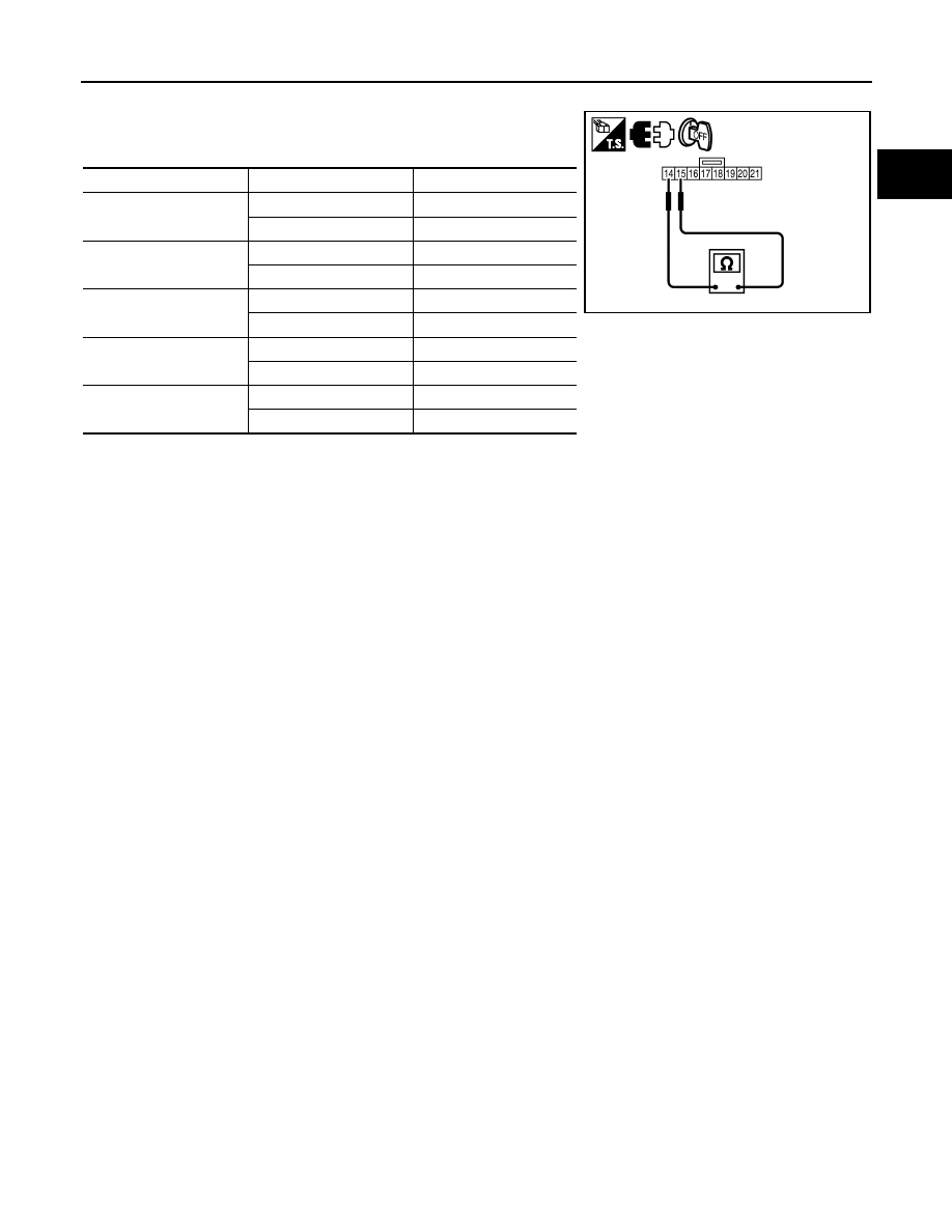
1. Disconnect combination switch (spiral cable) harness connector M102.
2. Check continuity between combination switch terminals 1 and 2
with pushing each switch.
If NG, replace ICC steering switch.
Switch
Condition
Resistance [
Ω]
MAIN switch
Pressed
Approx. 0
Released
Approx. 5,500
CANCEL switch
Pressed
Approx. 310
Released
Approx. 5,500
RESUME/ACCELERATE
switch
Pressed
Approx. 2,600
Released
Approx. 5,500
SET/COAST switch
Pressed
Approx. 1,400
Released
Approx. 5,500
DISTANCE switch
Pressed
Approx. 740
Released
Approx. 5,500
JMBIA0603ZZ
Нет комментариевНе стесняйтесь поделиться с нами вашим ценным мнением.
Текст