Infiniti QX56 (JA60). Manual — part 496
HEADLAMP AIMING SYSTEM (MANUAL)
EXL-13
< FUNCTION DIAGNOSIS >
C
D
E
F
G
H
I
J
K
M
A
B
EXL
N
O
P
HEADLAMP AIMING SYSTEM (MANUAL)
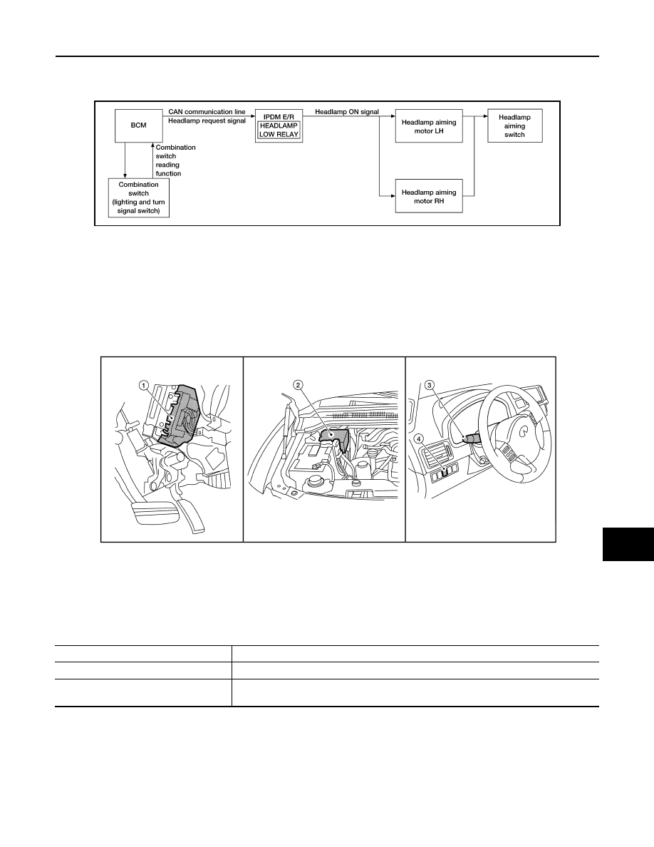
System Diagram
INFOID:0000000005146616
System Description
INFOID:0000000005146617
The headlamp aiming system (manual) controls the headlamp light axis height according to input from the
headlamp aiming switch. The variable internal resistance of the headlamp aiming switch controls the signal
ground of the headlamp aiming motors located on the front combination lamp LH and RH.
Component Parts Location
INFOID:0000000005146618
Component Description
INFOID:0000000005146619
AWLIA1717GB
1.
BCM M18, M20 (view with instrument
panel removed)
2.
IPDM E/R E121, E122, E123, E124
3.
Combination switch (lighting and turn
signal switch) M28
4.
Headlamp aiming switch M148
AWLIA0508ZZ
Part
Description
Headlamp aiming motor
Moves the headlamp up/down based on input from the headlamp aiming switch.
Headlamp aiming switch
Controls variable ground to the headlamp aiming motor signal to move the headlamp aim-
ing motor up/down.
EXL-14
< FUNCTION DIAGNOSIS >
FRONT FOG LAMP
FRONT FOG LAMP
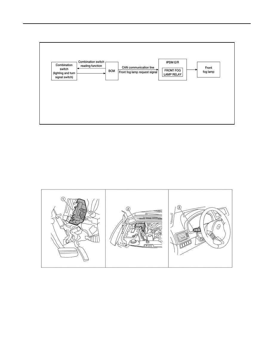
System Diagram
INFOID:0000000005369879
System Description
INFOID:0000000005369880
The front fog lamps are activated with the combination switch (lighting and turn signal switch). The combina-
tion switch (lighting and turn signal switch) signal to the BCM is monitored with the BCM combination switch
reading function. When the fog lamps are turned ON with the combination switch (lighting and turn signal
switch), the BCM sends a front fog lamp request signal via CAN communication lines to the IPDM E/R. The
IPDM E/R grounds the front fog lamp relay coil to activate the front fog lamps.
Component Parts Location
INFOID:0000000005146622
Component Description
INFOID:0000000005369881
FRONT FOG LAMP OPERATION
When the combination switch (lighting and turn signal switch) is in front fog lamp ON position and also in 1ST
or 2ND position or AUTO position (headlamp is ON), the BCM detects FR FOG ON and the HEAD LAMP1, 2
ON or the AUTO LIGHT ON. The BCM sends a front fog lamp request ON signal via the CAN communication
lines to the IPDM E/R. The IPDM E/R then turns ON the front fog lamp relay sending power to the front fog
lamps.
AWLIA1719GB
1.
BCM M18, M20 (view with instrument
panel removed)
2.
IPDM E/R E122, E123, E124
3.
Combination switch (lighting and turn
signal switch) M28
AWNIA0509ZZ
TURN SIGNAL AND HAZARD WARNING LAMPS
EXL-15
< FUNCTION DIAGNOSIS >
C
D
E
F
G
H
I
J
K
M
A
B
EXL
N
O
P
TURN SIGNAL AND HAZARD WARNING LAMPS
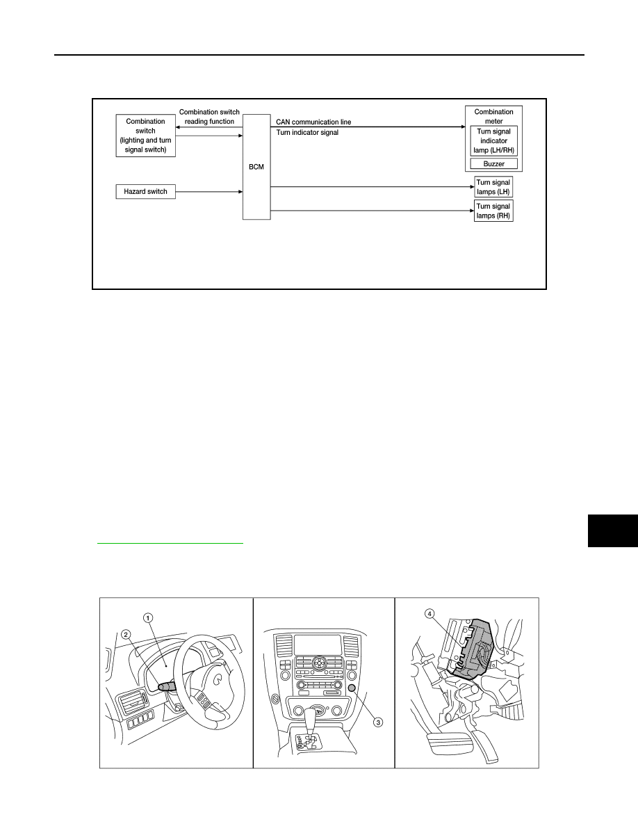
System Diagram
INFOID:0000000005146624
System Description
INFOID:0000000005146625
TURN SIGNAL OPERATION
When the combination switch (lighting and turn signal switch) is in LH or RH position with the ignition switch in
ON position, the BCM detects the TURN RH or TURN LH ON request. The BCM outputs the flasher signal to
the respective turn signal lamp. The BCM also sends a turn indicator signal ON request via the CAN commu-
nication lines to the combination meter. The combination meter then activates the appropriate turn signal indi-
cator and audible buzzer.
HAZARD LAMP OPERATION
When the hazard switch is in ON position, the BCM detects the hazard switch signal ON. The BCM outputs the
flasher signal (right and left). The BCM sends a hazard indicator signal ON request via the CAN communica-
tion lines to the combination meter. The combination meter then activates the hazard indicator and audible
buzzer.
REMOTE KEYLESS ENTRY OPERATION
The remote keyless entry receiver transmits a hazard request signal to the BCM, then BCM controls hazard
lamps.
.
Component Parts Location
INFOID:0000000005146626
AWLIA1721GB
AWLIA1628ZZ

EXL-16
< FUNCTION DIAGNOSIS >
TURN SIGNAL AND HAZARD WARNING LAMPS
Component Description
INFOID:0000000005146627
1.
Combination meter M23, M24
2.
Combination switch (lighting and turn
signal switch) M28
3.
Hazard switch M55
4.
BCM M18, M20 (view with instrument
panel removed)
Part name
Description
BCM
Controls turn signal and hazard flasher operation.
Combination switch (lighting and turn signal switch)
Lighting and turn signal switch requests are output to the BCM.
Hazard switch
Hazard flasher request signal is output to the BCM.
Combination meter
Outputs turn and hazard indicator as requested by the BCM.
Нет комментариевНе стесняйтесь поделиться с нами вашим ценным мнением.
Текст