Infiniti QX56 (JA60). Manual — part 728
PCS-34
< PRECAUTION >
[IPDM E/R]
PRECAUTIONS
5. When the repair work is completed, return the ignition switch to the
″LOCK″ position before connecting
the battery cables. (At this time, the steering lock mechanism will engage.)
6. Perform a self-diagnosis check of all control units using CONSULT-III.
PCS
IPDM E/R (INTELLIGENT POWER DISTRIBUTION MODULE ENGINE ROOM)
PCS-35
< REMOVAL AND INSTALLATION >
[IPDM E/R]
C
D
E
F
G
H
I
J
K
L
B
A
O
P
N
REMOVAL AND INSTALLATION
IPDM E/R (INTELLIGENT POWER DISTRIBUTION MODULE ENGINE
ROOM)
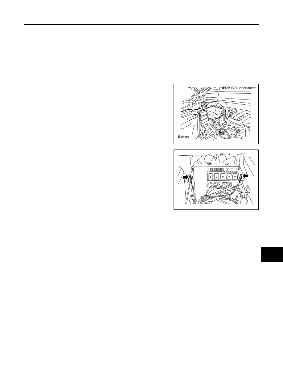
Removal and Installation of IPDM E/R
INFOID:0000000005146519
REMOVAL
1. Disconnect negative battery cable.
2. Remove IPDM E/R upper cover.
3. Release 2 clips and pull IPDM E/R up from case.
4. Disconnect IPDM E/R connectors and remove the IPDM E/R.
INSTALLATION
Installation is in the reverse order of removal.
WKIA1454E
WKIA1696E
PG
PG-1
ELECTRICAL & POWER CONTROL
C
D
E
F
G
H
I
J
K
L
B
SECTION
PG
A
O
P
N
CONTENTS
POWER SUPPLY, GROUND & CIRCUIT ELEMENTS
PRECAUTION . . . . . . . . . . . ...
PRECAUTIONS . . . . . . . . . . . . ...
Precaution Necessary for Steering Wheel Rota-
tion After Battery Disconnect . . . . . . . . .....
Precaution for Power Generation Variable Voltage
Control System . . . . . . . . . . . . . . ..
PREPARATION . . . . . . . . . . .
PREPARATION . . . . . . . . . . . . ...
Special Service Tool . . . . . . . . . . . .....
Commercial Service Tool . . . . . . . . . . ..
BASIC INSPECTION . . . . . . . . .
BATTERY . . . . . . . . . . . . . . .
How to Handle Battery . . . . . . . . . . . ..
Work Flow . . . . . . . . . . . . . . . .....
INSPECTION AND ADJUSTMENT . . . . . .
ADDITIONAL SERVICE WHEN REMOVING BAT-
TERY NEGATIVE TERMINAL . . . . . . . . .....
COMPONENT DIAGNOSIS . . . . . . ..
POWER SUPPLY ROUTING CIRCUIT . . . ...
Wiring Diagram — Battery Power Supply — . . .....
Wiring Diagram — Accessory Power Supply — . .
Wiring Diagram — Ignition Power Supply — . . ..
Fuse . . . . . . . . . . . . . . . . . .
Fusible Link . . . . . . . . . . . . . . . .
GROUND . . . . . . . . . . . . . . ...
Ground Distribution . . . . . . . . . . . . ..
HARNESS . . . . . . . . . . . . . . .
Harness Layout . . . . . . . . . . . . . ...
ELECTRICAL UNITS LOCATION . . . . .
Electrical Units Location . . . . . . . . . . ..
HARNESS CONNECTOR . . . . . . . . .
Description . . . . . . . . . . . . . . . ...
STANDARDIZED RELAY . . . . . . . . .
Description . . . . . . . . . . . . . . . ...
FUSE BLOCK - JUNCTION BOX (J/B) . . .
Terminal Arrangement . . . . . . . . . . . .
FUSE, FUSIBLE LINK AND RELAY BOX . .
Terminal Arrangement . . . . . . . . . . . .
IPDM E/R (INTELLIGENT POWER DISTRI-
BUTION MODULE ENGINE ROOM) . . . .
IPDM E/R Terminal Arrangement - Type A . . . .
IPDM E/R Terminal Arrangement - Type B . . . .
ON-VEHICLE REPAIR . . . . . . . . .
BATTERY . . . . . . . . . . . . . . ..
Removal and Installation . . . . . . . . . . .
SERVICE DATA AND SPECIFICATIONS
(SDS) . . . . . . . . . . . . . . .
SERVICE DATA AND SPECIFICATIONS
(SDS) . . . . . . . . . . . . . . . . .
PG-2
< PRECAUTION >
PRECAUTIONS
PRECAUTION
PRECAUTIONS
Precaution for Supplemental Restraint System (SRS) "AIR BAG" and "SEAT BELT
PRE-TENSIONER"
INFOID:0000000005260236
The Supplemental Restraint System such as “AIR BAG” and “SEAT BELT PRE-TENSIONER”, used along
with a front seat belt, helps to reduce the risk or severity of injury to the driver and front passenger for certain
types of collision. This system includes seat belt switch inputs and dual stage front air bag modules. The SRS
system uses the seat belt switches to determine the front air bag deployment, and may only deploy one front
air bag, depending on the severity of a collision and whether the front occupants are belted or unbelted.
Information necessary to service the system safely is included in the SR and SB section of this Service Man-
ual.
WARNING:
• To avoid rendering the SRS inoperative, which could increase the risk of personal injury or death in
the event of a collision which would result in air bag inflation, all maintenance must be performed by
an authorized NISSAN/INFINITI dealer.
• Improper maintenance, including incorrect removal and installation of the SRS, can lead to personal
injury caused by unintentional activation of the system. For removal of Spiral Cable and Air Bag
Module, see the SR section.
• Do not use electrical test equipment on any circuit related to the SRS unless instructed to in this
Service Manual. SRS wiring harnesses can be identified by yellow and/or orange harnesses or har-
ness connectors.
PRECAUTIONS WHEN USING POWER TOOLS (AIR OR ELECTRIC) AND HAMMERS
WARNING:
• When working near the Airbag Diagnosis Sensor Unit or other Airbag System sensors with the Igni-
tion ON or engine running, DO NOT use air or electric power tools or strike near the sensor(s) with a
hammer. Heavy vibration could activate the sensor(s) and deploy the air bag(s), possibly causing
serious injury.
• When using air or electric power tools or hammers, always switch the Ignition OFF, disconnect the
battery, and wait at least 3 minutes before performing any service.
Precaution Necessary for Steering Wheel Rotation After Battery Disconnect
INFOID:0000000005260237
NOTE:
• This Procedure is applied only to models with Intelligent Key system and NATS (NISSAN ANTI-THEFT SYS-
TEM).
• Remove and install all control units after disconnecting both battery cables with the ignition knob in the
″LOCK″ position.
• Always use CONSULT-III to perform self-diagnosis as a part of each function inspection after finishing work.
If DTC is detected, perform trouble diagnosis according to self-diagnostic results.
For models equipped with the Intelligent Key system and NATS, an electrically controlled steering lock mech-
anism is adopted on the key cylinder.
For this reason, if the battery is disconnected or if the battery is discharged, the steering wheel will lock and
steering wheel rotation will become impossible.
If steering wheel rotation is required when battery power is interrupted, follow the procedure below before
starting the repair operation.
OPERATION PROCEDURE
1. Connect both battery cables.
NOTE:
Supply power using jumper cables if battery is discharged.
2. Use the Intelligent Key or mechanical key to turn the ignition switch to the
″ACC″ position. At this time, the
steering lock will be released.
3. Disconnect both battery cables. The steering lock will remain released and the steering wheel can be
rotated.
4. Perform the necessary repair operation.
Нет комментариевНе стесняйтесь поделиться с нами вашим ценным мнением.
Текст