Infiniti QX56 (JA60). Manual — part 167

CCS-4
< BASIC INSPECTION >
DIAGNOSIS AND REPAIR WORKFLOW
• Perform the ICC system action test to check the ICC system operation status. Refer to
TIONAL SERVICE WHEN REPLACING CONTROL UNIT : Special Repair Requirement"
.
>> GO TO 2
2.
PERFORM SELF-DIAGNOSIS OF ICC UNIT
1. Perform self-diagnosis of ICC unit.
2. Check if DTC is detected.
Is any DTC detected?
YES
>> GO TO 3
NO
>> GO TO 4
3.
CHECK SELF-DIAGNOSIS RESULTS
1. Check the DTC detected in the self-diagnosis results.
2. Perform the relevant diagnosis by referring to the DTC index. Refer to
CCS-56, "Diagnostic Trouble Code
.
NOTE:
If “CAN COMM CIRCUIT [U1000]” (DTC 20) is displayed, start with the diagnosis for the CAN communication
system. Refer to
>> GO TO 5
4.
DIAGNOSIS BY SYMPTOM
Referring to the diagnosis chart by symptom, perform the relevant diagnosis. Refer to
.
>> GO TO 5
5.
REPAIR OR REPLACE APPLICABLE ITEM
Repair or replace applicable item.
>> GO TO 6
6.
CHECK AFTER REPAIRING OR REPLACING THE APPLICABLE ITEM
1. Erase DTC.
2. Perform the self-diagnosis for the ICC unit again after repairing or replacing the applicable item.
3. Check if DTC is detected.
Is any DTC detected?
YES
>> GO TO 3
NO
>> GO TO 7
7.
CHECK ICC SYSTEM
Test the ICC system for normal operation to see if the malfunction symptom is solved and no other symptoms
are present.
No symptoms?
YES
>> Inspection End.
NO
>> GO TO 4
CCS
INSPECTION AND ADJUSTMENT
CCS-5
< BASIC INSPECTION >
C
D
E
F
G
H
I
J
K
L
M
B
N
P
A
INSPECTION AND ADJUSTMENT
ADDITIONAL SERVICE WHEN REPLACING CONTROL UNIT
ADDITIONAL SERVICE WHEN REPLACING CONTROL UNIT : Description
INFOID:0000000005145971
Always perform the laser beam aiming adjustment after replacing the ICC unit. In addition, test the ICC sys-
tem operations to see if it functions normally.
ADDITIONAL SERVICE WHEN REPLACING CONTROL UNIT : Special Repair Re-
quirement
INFOID:0000000005145972
1.
LASER BEAM AIMING ADJUSTMENT
Adjust laser beam aiming. Refer to
CCS-5, "LASER BEAM AIMING ADJUSTMENT : Outline of Laser Beam
.
>> GO TO 2
2.
ICC SYSTEM ACTION TEST
1. Perform the ICC system operation test. Refer to
CCS-8, "ACTION TEST : ICC System Running Test"
2. Check that the ICC system operates normally.
>> INSPECTION END.
LASER BEAM AIMING ADJUSTMENT
LASER BEAM AIMING ADJUSTMENT : Outline of Laser Beam Aiming Adjustment
Procedure
INFOID:0000000005145973
CAUTION:
• The laser beam aiming adjustment cannot be performed without CONSULT-III.
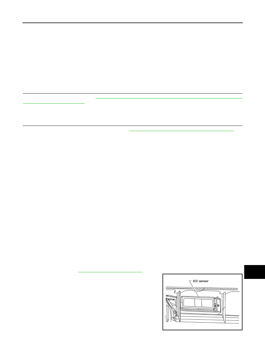
• The laser beam aiming adjustment must be performed every time the ICC sensor is removed,
installed or has been moved as a result of a collision.
1. Prepare the vehicle and the work area.
2. Set up the ICC target board. For details, refer to Technical Service Bulletin.
3. Adjust the sensor following the procedure on CONSULT-III.
4. Check system operation after the adjustment.
LASER BEAM AIMING ADJUSTMENT : Preparation
INFOID:0000000005145974
• Place the vehicle on level ground. Shift the transmission into "P" position and release the parking brake.
• Adjust the tire pressure to the specified value.
• See that there is no load in the vehicle. Coolant, engine oil and fuel should be filled to correct level.
• Check that the vehicle suspension has been adjusted to the standard height by the load leveling rear air sus-
pension system. Refer to
• Clean the sensor with a soft cloth.
Tool number
: KV99110100 (J-45718)
LKIA0632E
CCS-6
< BASIC INSPECTION >
INSPECTION AND ADJUSTMENT
LASER BEAM AIMING ADJUSTMENT : Setting up the ICC Target Board
INFOID:0000000005145975
CAUTION:
Accuracy in setting up the ICC target board is essential for the laser beam aiming adjustment.
For details, refer to Technical Service Bulletin.
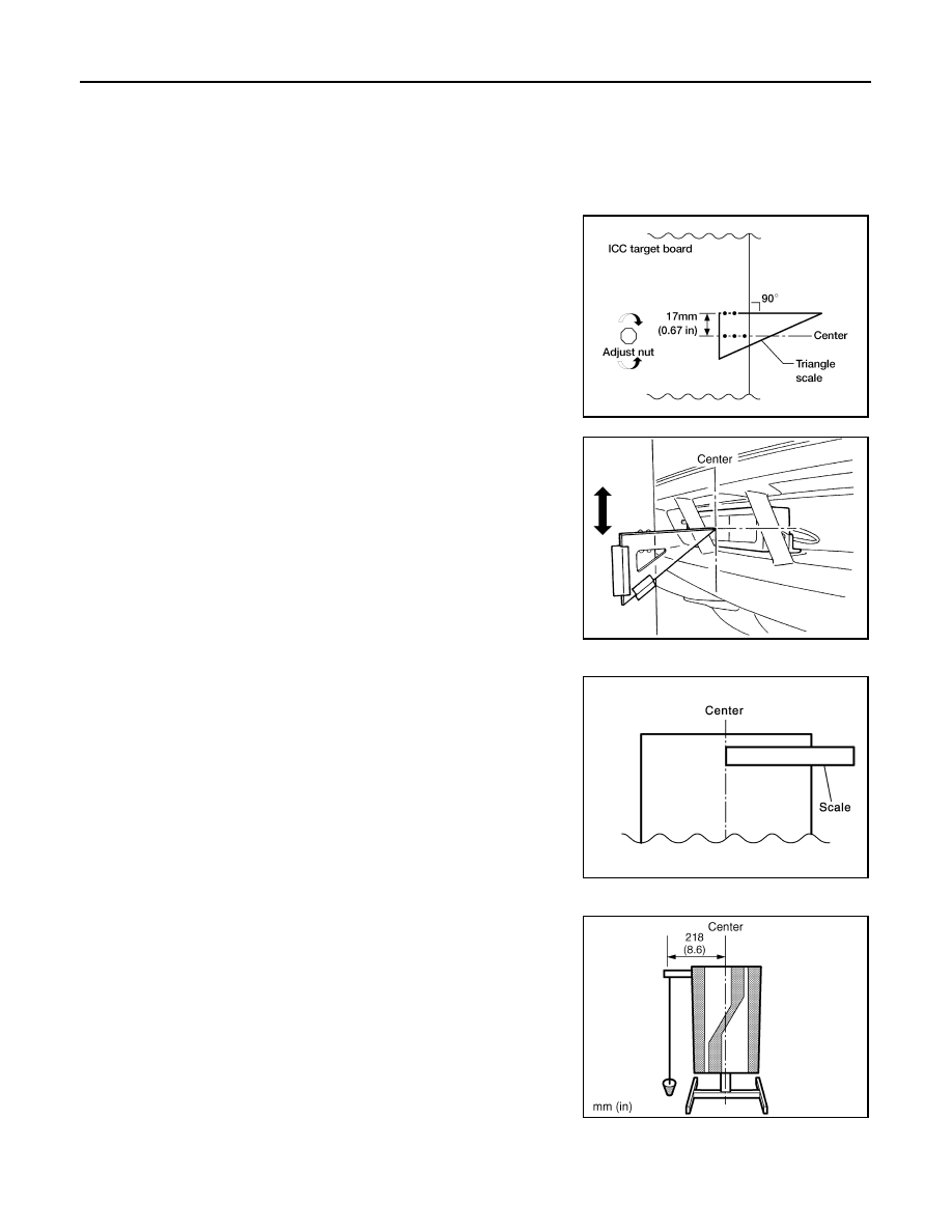
ADJUSTING HEIGHT OF THE TARGET
1. Attach a triangle scale as shown.
2. Adjust the height of the target stand so that the point of the trian-
gle aims above the center of the ICC sensor.
ADJUSTING THE POSITION OF THE TARGET BOARD STRING
1. Attach a scale or straightedge (at least 350 mm [14 in] or
longer).
2. Suspend a string with a weight on the end 218 mm
(8.6 in) to the left side of the target board center.
POSITIONING THE TARGET
1. Suspend a string with weights on each end over the centerline of the vehicle. The string should lay over
the center of the front and back bumpers. Mark these centerpoints on the ground at each weight.
WKIA1849E
WKIA2039E
SKIA1211E
WKIA2040E
CCS
INSPECTION AND ADJUSTMENT
CCS-7
< BASIC INSPECTION >
C
D
E
F
G
H
I
J
K
L
M
B
N
P
A
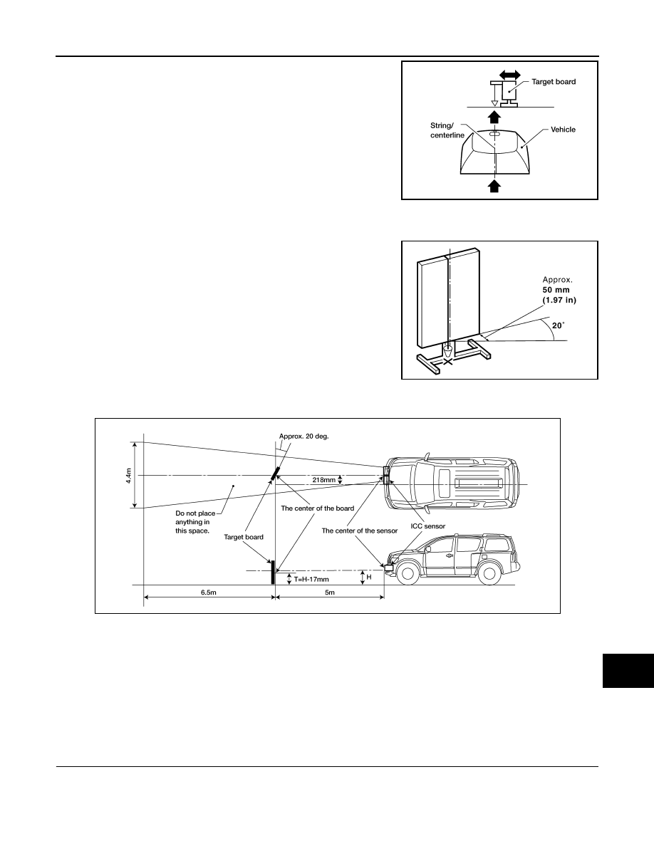
2. Connect the two center points using a string. Extend the string
an additional 5 m (16 ft) beyond the front centerpoint and mark
the floor. Position the target board weight on this mark.
3. Relocate the suspended string from the left side of the target board to the center of the target board. Mark
this point on the ground.
4. Pivot the target board on its center mark 20
° to either side.
NOTE:
Approx. 50 mm (1.97 in) shift will produce a 20
° movement.
5. Remove any items in the shaded space shown in the figure.
NOTE:
In case the background space shown in the illustration is not available, or if the background is light col-
ored, place a 400 mm (15.75 in) long frosted black board or black cloth to both sides of the target board.
LASER BEAM AIMING ADJUSTMENT : Sensor Adjustment
INFOID:0000000005145976
CAUTION:
Never view ICC sensor unit body window directly during laser beam aiming adjustment.
NOTE:
Complete all necessary steps for laser beam adjustment until the CONSULT-III indicates "COMPLETED". If
the procedure does not complete, the ICC system is inoperable.
1.
SET CONSULT-III TO THE LASER BEAM AIMING ADJUSTMENT MODE
1. Connect CONSULT-III and select "Work Support" of "ICC".
2. Select "LASER BEAM ADJUST".
3. Touch "START".
WKIA1851E
PKIA2589E
WKIA1858E
Нет комментариевНе стесняйтесь поделиться с нами вашим ценным мнением.
Текст