Infiniti QX56 (JA60). Manual — part 425
EC-352
< COMPONENT DIAGNOSIS >
[VK56DE]
P1574 ASCD VEHICLE SPEED SENSOR
OK or NG
OK
>> GO TO 3.
NG
>> Repair or replace.
3.
CHECK COMBINATION METER FUNCTION
Check combination meter function.
>> INSPECTION END
P1805 BRAKE SWITCH
EC-353
< COMPONENT DIAGNOSIS >
[VK56DE]
C
D
E
F
G
H
I
J
K
L
M
A
EC
N
P
O
P1805 BRAKE SWITCH
Description
INFOID:0000000005149417
Brake switch signal is applied to the ECM through the stop lamp switch when the brake pedal is depressed.
This signal is used mainly to decrease the engine speed when the vehicle is driving.
On Board Diagnosis Logic
INFOID:0000000005149418
The MIL will not light up for this self-diagnosis.
FAIL-SAFE MODE
When the malfunction is detected, the ECM enters fail-safe mode.
DTC Confirmation Procedure
INFOID:0000000005149419
1. Turn ignition switch ON.
2. Fully depress the brake pedal for at least 5 seconds.
3. Erase the DTC with CONSULT-III.
4. Check 1st trip DTC.
5. If 1st trip DTC is detected, go to
Diagnosis Procedure
INFOID:0000000005149420
1.
CHECK OVERALL FUNCTION-II
With CONSULT-III
Check “BRAKE SW2” indication in “DATA MONITOR” mode.
Without CONSULT-III
DTC No.
Trouble diagnosis name
DTC detecting condition
Possible cause
P1805
1805
Brake switch
A brake switch signal is not sent to ECM for ex-
tremely long time while the vehicle is driving.
• Harness or connectors
(Stop lamp switch circuit is open or short-
ed.)
• Stop lamp switch
Engine operating condition in fail-safe mode
ECM controls the electric throttle control actuator by regulating the throttle opening to a small range.
Therefore, acceleration will be poor.
Vehicle condition
Driving condition
When engine is idling
Normal
When accelerating
Poor acceleration
CONDITION
INDICATION
Brake pedal: Fully released
OFF
Brake pedal: Slightly depressed
ON
EC-354
< COMPONENT DIAGNOSIS >
[VK56DE]
P1805 BRAKE SWITCH
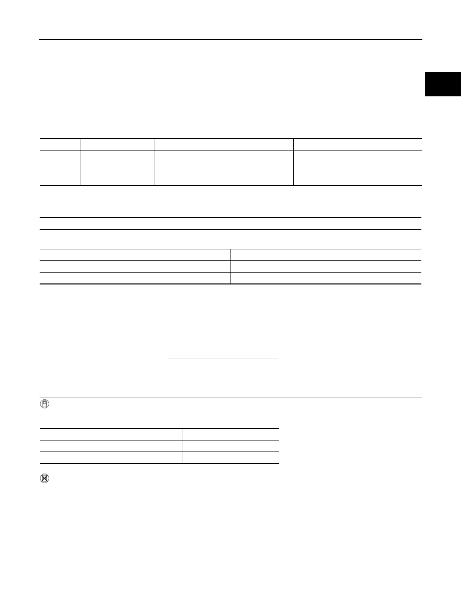
Check voltage between ECM terminal 101 and ground under the fol-
lowing conditions.
OK or NG
OK
>> GO TO 6.
NG
>> GO TO 2.
2.
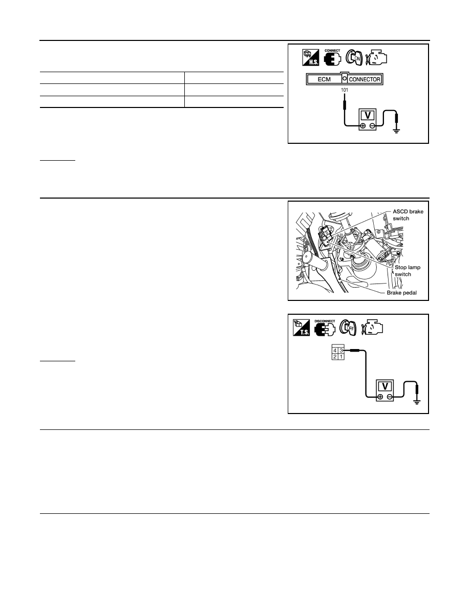
CHECK STOP LAMP SWITCH POWER SUPPLY CIRCUIT
1. Disconnect stop lamp switch harness connector.
2. Check voltage between stop lamp switch terminal 3 and ground
with CONSULT-III or tester.
OK or NG
OK
>> GO TO 4.
NG
>> GO TO 3.
3.
DETECT MALFUNCTIONING PART
Check the following.
• Harness connectors M31, E152
• Fuse block (J/B) connector M60
• 10 A fuse (No. 20)
• Harness for open and short between stop lamp switch and battery
>> Repair open circuit or short to ground or short to power in harness or connectors.
4.
CHECK STOP LAMP SWITCH INPUT SIGNAL CIRCUIT FOR OPEN AND SHORT
1. Turn ignition switch OFF.
2. Disconnect ECM harness connector.
3. Check harness continuity between ECM terminal 101 and stop lamp switch terminal 4.
Refer to Wiring Diagram.
4. Also check harness for short to ground and short to power.
CONDITION
VOLTAGE
Brake pedal: Fully released
Approximately 0 V
Brake pedal: Slightly depressed
Battery voltage
PBIB1537E
BBIA0373E
Voltage: Battery voltage
PBIB2102E
Continuity should exist.
P1805 BRAKE SWITCH
EC-355
< COMPONENT DIAGNOSIS >
[VK56DE]
C
D
E
F
G
H
I
J
K
L
M
A
EC
N
P
O
OK or NG
OK
>> GO TO 5.
NG
>> Repair open circuit or short to ground or short to power in harness or connectors.
5.
CHECK STOP LAMP SWITCH
EC-355, "Component Inspection"
OK or NG
OK
>> GO TO 6.
NG
>> Replace stop lamp switch.
6.
CHECK INTERMITTENT INCIDENT
GI-35, "How to Check Terminal"
GI-38, "Intermittent Incident"
>> INSPECTION END
Component Inspection
INFOID:0000000005149421
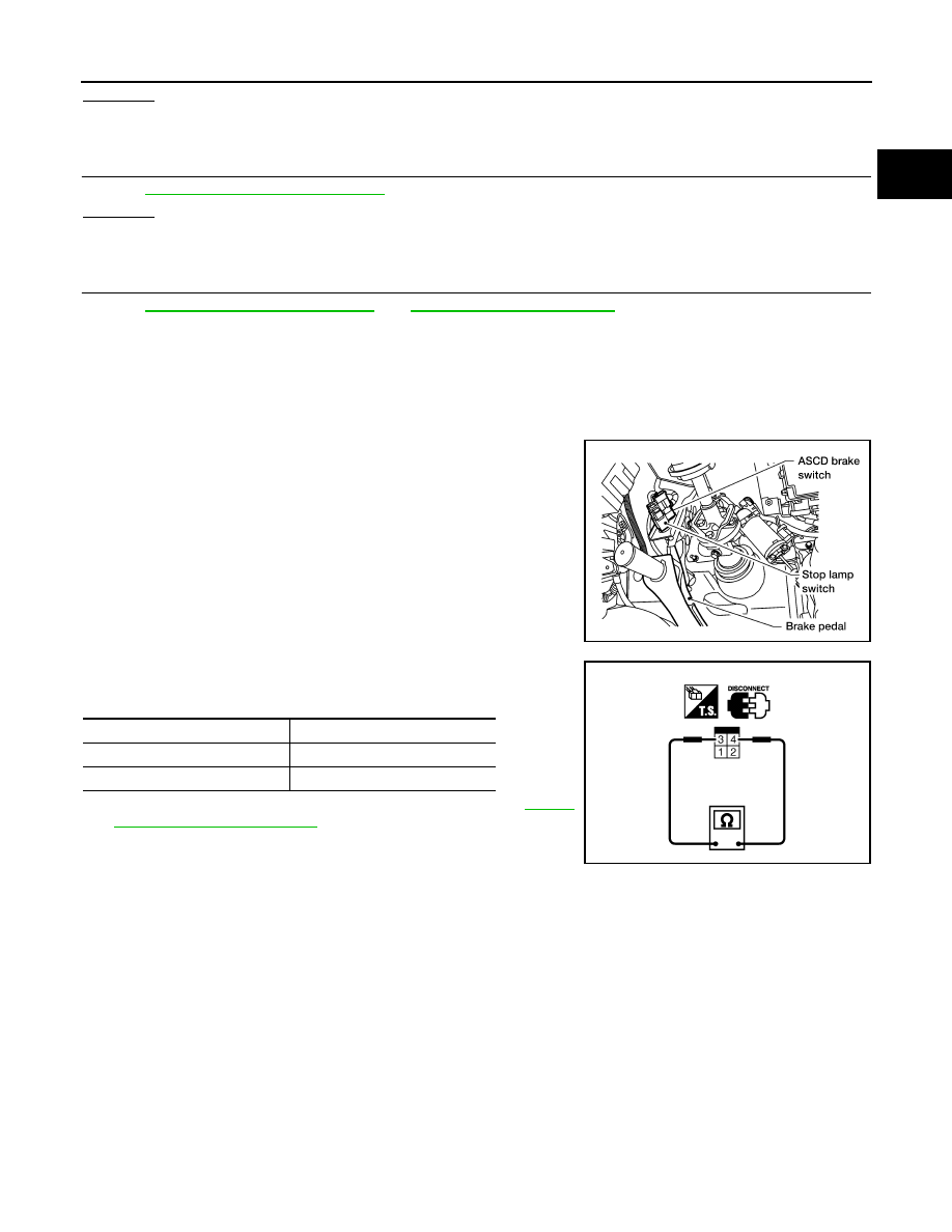
STOP LAMP SWITCH
1. Disconnect stop lamp switch harness connector.
2. Check continuity between stop lamp switch terminals 3 and 4
under the following conditions.
3. If NG, adjust stop lamp switch installation, refer to
, and perform step 2 again.
BBIA0373E
Conditions
Continuity
Brake pedal: Fully released
Should not exist.
Brake pedal: Slightly depressed
Should exist.
PBIB2103E
Нет комментариевНе стесняйтесь поделиться с нами вашим ценным мнением.
Текст