Infiniti QX56 (JA60). Manual — part 72
AV-96
< COMPONENT DIAGNOSIS >
[AUDIO SYSTEM]
REAR DOOR TWEETER
REAR DOOR TWEETER
Description
INFOID:0000000005146333
The AV control unit sends audio signals to the BOSE speaker amp. The BOSE speaker amp. amplifies the
audio signals before sending them to the rear tweeters using the audio signal circuits.
Diagnosis Procedure
INFOID:0000000005146334
Regarding Wiring Diagram information, refer to
.
1.
HARNESS CHECK
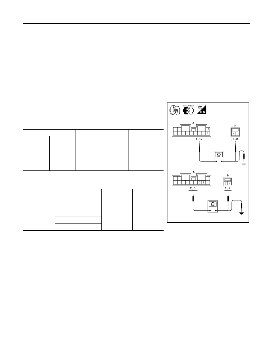
1. Disconnect BOSE speaker amp. connectors M112 and suspect
tweeter connector.
2. Check continuity between BOSE speaker amp. harness connec-
tors M112 (A) and suspect tweeter harness connector (B).
3. Check continuity between BOSE speaker amp. harness connec-
tors M112 (A) and ground.
Are the continuity test results as specified?
YES
>> GO TO 2.
NO
>> • Check connector housings for disconnected or loose terminals.
• Repair harness or connector.
2.
REAR TWEETER SIGNAL CHECK
A
B
Continuity
Connector
Terminal
Connector
Terminal
M112
1
D207
1
Yes
10
2
2
D307
1
3
2
A
—
Continuity
Connector
Terminal
M112
1
Ground
No
10
2
3
ALNIA0352GB
AV
REAR DOOR TWEETER
AV-97
< COMPONENT DIAGNOSIS >
[AUDIO SYSTEM]
C
D
E
F
G
H
I
J
K
L
M
B
A
O
P
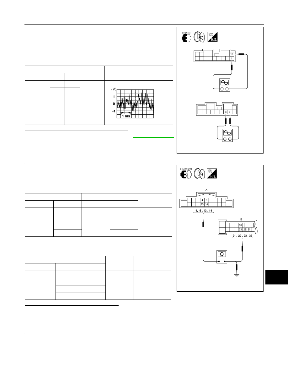
1. Connect BOSE speaker amp. connectors and suspect tweeter
connector.
2. Turn ignition switch to ACC.
3. Push “POWER” switch.
4. Check the signal between BOSE speaker amp. harness connec-
tors M112 terminals with CONSULT-III or oscilloscope.
Are audio signal voltage readings as specified?
YES
>> Replace suspect tweeter. Refer to
.
NO
>> GO TO 3.
3.
HARNESS CHECK
1. Disconnect AV control unit connector M42 and BOSE speaker
amp. connector M113.
2. Check continuity between AV control unit harness connector
M42 (A) and BOSE speaker amp. harness connector M113 (B).
3. Check continuity between AV control unit harness connector
M42 (A) and ground.
Are the continuity test results as specified?
YES
>> GO TO 4.
NO
>> • Check connector housings for disconnected or loose terminals.
• Repair harness or connector.
4.
REAR DOOR SPEAKER SIGNAL CHECK
Connector
Terminals
Condition
Reference
signal
(+)
(-)
M112
1
10
Receive
audio sig-
nal
2
3
ALNIA0843GB
SKIA0177E
A
B
Continuity
Connector
Terminal
Connector
Terminal
M42
4
M113
21
Yes
5
22
13
23
14
33
A
—
Continuity
Connector
Terminal
M42
4
Ground
No
5
13
14
ALNIA0418GB
AV-98
< COMPONENT DIAGNOSIS >
[AUDIO SYSTEM]
REAR DOOR TWEETER
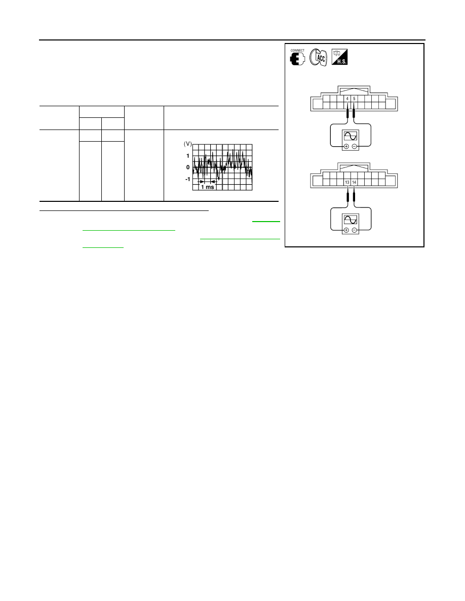
1. Connect AV control unit connector M42 and BOSE speaker
amp. connector M113.
2. Turn ignition switch to ACC.
3. Push “POWER” switch.
4. Check the signal between AV control unit harness connector
M42 terminals with CONSULT-III or oscilloscope.
Is the audio signal voltage reading as specified?
YES
>> Replace BOSE speaker amp. Refer to
.
NO
>> Replace AV control unit. Refer to
Connector
Terminals
Condition
Reference
signal
(+)
(-)
M42
4
5
Receive
audio sig-
nal
13
14
ALNIA0419GB
SKIA0177E
AV
BACK DOOR SPEAKER
AV-99
< COMPONENT DIAGNOSIS >
[AUDIO SYSTEM]
C
D
E
F
G
H
I
J
K
L
M
B
A
O
P
BACK DOOR SPEAKER
Description
INFOID:0000000005146335
The AV control unit sends audio signals to the BOSE speaker amp. The BOSE speaker amp. amplifies the
audio signals before sending them to the back door speakers using the audio signal circuits.
Diagnosis Procedure
INFOID:0000000005146336
Regarding Wiring Diagram information, refer to
.
1.
HARNESS CHECK
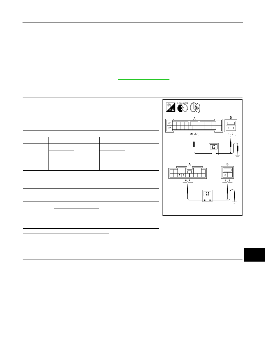
1. Disconnect BOSE speaker amp. connectors and suspect
speaker connector.
2. Check continuity between BOSE speaker amp. harness connec-
tors M112 and M113 (A) and suspect speaker harness connec-
tor (B).
3. Check continuity between BOSE speaker amp. harness connec-
tors M112 and M113 (A) and ground.
Are the continuity test results as specified?
YES
>> GO TO 2.
NO
>> • Check connector housings for disconnected or loose terminals.
• Repair harness or connector.
2.
BACK DOOR SPEAKER SIGNAL CHECK
A
B
Continuity
Connector
Terminal
Connector
Terminal
M112
6
D518
1
Yes
7
2
M113
37
D716
1
27
2
A
—
Continuity
Connector
Terminal
M112
6
Ground
No
7
M113
27
37
ALNIA0663GB
Нет комментариевНе стесняйтесь поделиться с нами вашим ценным мнением.
Текст