Infiniti QX56 (JA60). Manual — part 442
EC-420
< COMPONENT DIAGNOSIS >
[VK56DE]
REFRIGERANT PRESSURE SENSOR
OK or NG
OK
>> GO TO 3.
NG
>> Repair or replace ground connections.
3.
CHECK REFRIGERANT PRESSURE SENSOR POWER SUPPLY CIRCUIT
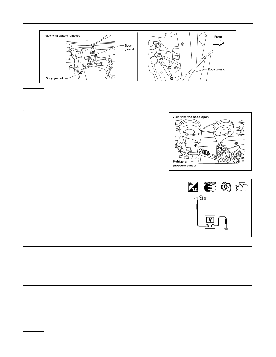
1. Disconnect refrigerant pressure sensor harness connector.
2. Turn ignition switch ON.
3. Check voltage between refrigerant pressure sensor terminal 1
and ground with CONSULT-III or tester.
OK or NG
OK
>> GO TO 5.
NG
>> GO TO 4.
4.
DETECT MALFUNCTIONING PART
Check the following.
• Harness connectors E5, F14
• Harness for open or short between ECM and refrigerant pressure sensor
>> Repair harness or connectors.
5.
CHECK REFRIGERANT PRESSURE SENSOR GROUND CIRCUIT FOR OPEN AND SHORT
1. Turn ignition switch OFF.
2. Disconnect ECM harness connector.
3. Check harness continuity between refrigerant pressure sensor terminal 3 and ECM terminal 67.
Refer to Wiring Diagram.
4. Also check harness for short to ground and short to power.
OK or NG
OK
>> GO TO 7.
NG
>> GO TO 6.
BBIA0354E
BBIA0445E
Voltage: Approximately 5 V
PBIB0188E
Continuity should exist.

REFRIGERANT PRESSURE SENSOR
EC-421
< COMPONENT DIAGNOSIS >
[VK56DE]
C
D
E
F
G
H
I
J
K
L
M
A
EC
N
P
O
6.
DETECT MALFUNCTIONING PART
Check the following.
• Harness connectors E5, F14
• Harness for open or short between ECM and refrigerant pressure sensor
>> Repair open circuit or short to ground or short to power in harness or connectors.
7.
CHECK REFRIGERANT PRESSURE SENSOR INPUT SIGNAL CIRCUIT FOR OPEN AND SHORT
1. Check harness continuity between ECM terminal 70 and refrigerant pressure sensor terminal 2.
Refer to Wiring Diagram.
2. Also check harness for short to ground and short to power.
OK or NG
OK
>> GO TO 9.
NG
>> GO TO 8.
8.
DETECT MALFUNCTIONING PART
Check the following.
• Harness connectors E5, F14
• Harness for open or short between ECM and refrigerant pressure sensor
>> Repair open circuit or short to ground or short to power in harness or connectors.
9.
CHECK INTERMITTENT INCIDENT
GI-35, "How to Check Terminal"
GI-38, "Intermittent Incident"
OK or NG
OK
>> Replace refrigerant pressure sensor.
NG
>> Repair or replace.
Continuity should exist.
EC-422
< ECU DIAGNOSIS >
[VK56DE]
ECM
ECU DIAGNOSIS
ECM
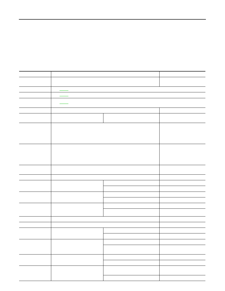
CONSULT-lll Reference Value in Data Monitor Mode
INFOID:0000000005149492
Remarks:
z
Specification data are reference values.
z
Specification data are output/input values which are detected or supplied by the ECM at the connector.
* Specification data may not be directly related to their components signals/values/operations.
i.e. Adjust ignition timing with a timing light before monitoring IGN TIMING, because the monitor may show the specification data in spite of the
ignition timing not being adjusted to the specification data. This IGN TIMING monitors the data calculated by the ECM according to the signals
input from the camshaft position sensor and other ignition timing related sensors.
MONITOR ITEM
CONDITION
SPECIFICATION
ENG SPEED
• Run engine and compare CONSULT-IIl value with the tachometer indica-
tion.
Almost the same speed as the
tachometer indication.
MAS A/F SE-B1
See
B/FUEL SCHDL
See
A/F ALPHA-B1
A/F ALPHA-B2
See
COOLAN TEMP/S
• Engine: After warming up
More than 70
°C (158°F)
A/F SEN1 (B1)
A/F SEN1 (B2)
• Engine: After warming up
Maintaining engine speed at 2,000 rpm Fluctuates around 2.2 V
HO2S2 (B1)
HO2S2 (B2)
• Revving engine from idle to 3,000 rpm quickly after the following conditions
are met.
- Engine: After warming up
- Keeping the engine speed between 3,500 and 4,000 rpm for 1 minute and
at idle for 1 minute under no load
0 - 0.3V
←→ Approx. 0.6 - 1.0V
HO2S2 MNTR (B1)
HO2S2 MNTR (B2)
• Revving engine from idle to 3,000 rpm quickly after the following conditions
are met.
- Engine: After warming up
- Keeping the engine speed between 3,500 and 4,000 rpm for 1 minute and
at idle for 1 minute under no load
LEAN
←→ RICH
VHCL SPEED SE
• Turn drive wheels and compare CONSULT-IIl value with the speedometer
indication.
Almost the same speed as the
speedometer indication
BATTERY VOLT
• Ignition switch: ON (Engine stopped)
11 - 14V
ACCEL SEN 1
• Ignition switch: ON
(Engine stopped)
Accelerator pedal: Fully released
0.5 - 1.0V
Accelerator pedal: Fully depressed
4.2 - 4.8V
ACCEL SEN 2*
1
• Ignition switch: ON
(Engine stopped)
Accelerator pedal: Fully released
0.5 - 1.0V
Accelerator pedal: Fully depressed
4.2 - 4.8V
TP SEN 1-B1
TP SEN 2-B1
• Ignition switch: ON
(Engine stopped)
• Selector lever: D
Accelerator pedal: Fully released
More than 0.36V
Accelerator pedal: Fully depressed
Less than 4.75V
EVAP SYS PRES
• Ignition switch: ON
Approx. 1.8 - 4.8V
START SIGNAL
• Ignition switch: ON
→ START → ON
OFF
→ ON → OFF
CLSD THL POS
• Ignition switch: ON
(Engine stopped)
Accelerator pedal: Fully released
ON
Accelerator pedal: Slightly depressed
OFF
AIR COND SIG
• Engine: After warming up, idle the
engine
Air conditioner switch: OFF
OFF
Air conditioner switch: ON
(Compressor operates.)
ON
P/N POSI SW
• Ignition switch: ON
Selector lever: P or N
ON
Selector lever: Except above
OFF
PW/ST SIGNAL
• Engine: After warming up, idle the
engine
Steering wheel: Not being turned
(Forward direction)
OFF
Steering wheel: Being turned
ON

ECM
EC-423
< ECU DIAGNOSIS >
[VK56DE]
C
D
E
F
G
H
I
J
K
L
M
A
EC
N
P
O
LOAD SIGNAL
• Ignition switch: ON
Rear window defogger switch is ON
and/or lighting switch is in 2nd.
ON
Rear window defogger switch is OFF
and lighting switch is OFF.
OFF
IGNITION SW
• Ignition switch: ON
→ OFF → ON
ON
→ OFF → ON
HEATER FAN SW
• Engine: After warming up, idle the
engine
Heater fan control switch: ON
ON
Heater fan control switch: OFF
OFF
BRAKE SW
• Ignition switch: ON
Brake pedal: Fully released
OFF
Brake pedal: Slightly depressed
ON
INJ PULSE-B1
INJ PULSE-B2
• Engine: After warming up
• Selector lever: P or N
• Air conditioner switch: OFF
• No load
Idle
2.0 - 2.8 msec
2,000 rpm
1.9 - 2.9 msec
IGN TIMING
• Engine: After warming up
• Selector lever: P or N
• Air conditioner switch: OFF
• No load
Idle
10
° - 20° BTDC
2,000 rpm
25
° - 45° BTDC
CAL/LD VALUE
• Engine: After warming up
• Selector lever: P or N
• Air conditioner switch: OFF
• No load
Idle
14% - 33%
2,500 rpm
12% - 25%
MASS AIRFLOW
• Engine: After warming up
• Selector lever: P or N
• Air conditioner switch: OFF
• No load
Idle
3.0 - 9.0 g·m/s
2,500 rpm
9.0 - 28.0 g·m/s
PURG VOL C/V
• Engine: After warming up
• Selector lever: P or N
• Air conditioner switch: OFF
• No load
Idle
(Accelerator pedal: Not depressed
even slightly, after engine starting.)
0%
2,000 rpm
—
INT/V TIM (B1)
INT/V TIM (B2)
• Engine: After warming up
• Selector lever: P or N
• Air conditioner switch: OFF
• No load
Idle
−5° - 5°CA
2,000 rpm
Approx. 0
° - 20°CA
INT/V SOL (B1)
INT/V SOL (B2)
• Engine: After warming up
• Selector lever: P or N
• Air conditioner switch: OFF
• No load
Idle
0% - 2%
2,000 rpm
Approx. 25% - 50%
AIR COND RLY
• Engine: After warming up, idle the
engine
Air conditioner switch: OFF
OFF
Air conditioner switch: ON
(Compressor: Operates)
ON
FUEL PUMP RLY
• For 1 second after turning ignition switch ON
• Engine running or cranking
ON
• Except above conditions
OFF
VENT CONT/V
• Ignition switch: ON
OFF
THRTL RELAY
• Ignition switch: ON
ON
COOLING FAN
• Engine: After warming up, idle the
engine
• Air conditioner switch: OFF
Engine coolant temperature: 99
°C
(210
°F) or less
OFF
Engine coolant temperature: 100
°C
(212
°F) or more
HI
HO2S2 HTR (B1)
HO2S2 HTR (B2)
• Engine speed: Below 3,600 rpm after the following conditions are met.
- Engine: After warming up
- Keeping the engine speed between 3,500 and 4,000 rpm for 1 minute and
at idle for 1 minute under no load
ON
• Engine speed: Above 3,600 rpm
OFF
MONITOR ITEM
CONDITION
SPECIFICATION
Нет комментариевНе стесняйтесь поделиться с нами вашим ценным мнением.
Текст